Section 11 – Testing, Approval and Checking of Measuring, Recording and Sampling Devices
Part 11A – General Guidelines for Device Certification and System Validation by ICAR
Overview: Guidelines for Testing, Certification and Checking of Measuring, Recording and Sampling Devices or Systems
Introduction
This overview summarizes the content of Section 11 of the ICAR Guidelines, introducing the principles and procedures developed for testing and certification of measuring, recording, and sampling devices and sensor systems by ICAR. The guidelines for Section 11 are grouped into five areas, with specific and relevant procedures within each section.
Section A: General Guidelines for Device Certification and System Validation
Section B: Testing of Measuring, Recording, and Sampling Devices for ICAR Certification
Section C: Testing of Sensor Systems for ICAR Validation
Section D: Guidelines and Best Practices for Animal/Sample Identification and Data Handling
Section E: Procedures for ICAR Member and Manufacturer Reporting
Device Certification and System Validation
ICAR testing may be of a specific measuring, recording and/or sampling device or of a sensor system that may include a device, animal identification system, controller and/or data transfer protocols.
Device Certification is the final stage of the ICAR testing and certification process for measuring, recording and sampling devices. ICAR-certified devices meet the ICAR guidelines provided the manufacturer of the device meets the conditions for certification as outlined in 2.2 of Procedure 1.
System Validation is the final stage of the ICAR testing and validation process for sensor systems. ICAR-validated sensor systems have demonstrated through ICAR testing that the system delivers data as described in the test report and the manufacturer of the system meets the conditions for validation outlined in 3.2 of Procedure 1.
Scope
Section 11 of the ICAR Guidelines covers the testing and certification or validation procedures from the submission of the application by the manufacturer to the testing of the device, the device certification or system validation, and the publication of the test results on the ICAR website. In addition, Section 11 covers the labeling and the routine checking of the certified devices or validated systems. Finally, the annual reporting by manufacturers and ICAR Members regarding certified devices or validated systems is also included in the certification scheme.
| Table 1. Steps, actions, and responsibilities in the ICAR certification procedure. | ||
|---|---|---|
| Step | Action | Responsibility |
| 1 | Application for device or system testing | Manufacturer (or dealer) |
| 2 | Review of application & relevant documentation | ICAR Secretariat & MRSD-SC Chair |
| 3 | Selection of Test Centre | MRSD-SC Chair |
| 4 | Drafting of test plan | Test Centre |
| 5 | Review and approval of test plan | Test Centres & MRSD-SC Chair |
| 6 | Issuance of umbrella contract and invoicing | ICAR Secretariat |
| 7 | Testing and compilation of report | Test Centre |
| 8 | Test report review | MRSD-SC & Test Centres |
| 9 | Sharing of test report with applicant & ICAR Board | ICAR Secretariat |
| 10 | ICAR certification/validation | ICAR Secretariat |
| 11 | Publication on ICAR website | ICAR Secretariat |
| 12 | Labeling procedure of certified device | Manufacturer & ICAR Secretariat |
| 13 | Annual reporting on certified devices or validated systems | Manufacturer & ICAR Members |

Application
The procedure for any type of test and certification or validation starts with an application submitted by the manufacturer/dealer to the ICAR Secretariat. Following the payment of a fixed application fee by the applicant, the ICAR Secretariat checks the application form and related documentation and passes them to the Chair of the ICAR Measuring, Recording, and Sampling Devices Sub-Committee (MRSD-SC), who establishes the test procedures and selects the Test Centre1 that will carry out the test. An umbrella contract and the invoice are sent to the applicant, who must take care of the payment before the test starts. The ICAR Secretariat coordinates financial transactions between manufacturers, Test Centres, and ICAR.
The Test Centre prepares the test plan, including time schedule and costs. For the test to begin, the manufacturer must send all the necessary devices and accessories to the Test Centre. In addition, all manuals, documents, and procedures should be provided to the Test Centre. The devices and accessories remain under the property of ICAR.
For full details, refer to Procedure 1 - Procedure for Application for Testing of Measuring, Recording and Sampling Devices or Sensor Systems.
Testing
Types of tests
ICAR offers a range of tests based on the device type: i) traditional milk meters or devices, ii) AMS -automatic/robotic milking systems and sampling shuttles or trays, iii) other measuring or recording devices, and iv) sensor devices/systems.
In case of new devices or systems, a full test is carried out, while for modified devices or systems a partial test or a desk review may be required, according to the decision of the MRSD-SC Chair and the Test Centre.
| Table 2. Types of tests of measuring, recording, and sampling devices. | ||
|---|---|---|
| Type of device | Link to test procedure | |
| Traditional milk meters
Other measuring devices |
Procedure 4 - Procedure for Testing of Traditional Recording and Sampling Devices | |
| Automatic milking systems | Procedure 5 - Procedure for Testing of Automatic Milk Recording and Sampling Systems | |
| Sensor systems | Procedure 8 - Procedure for Validation of Sensor Systems | |
Test Centres
Testing is conducted by ICAR accredited Test Centres1. Each test is contracted by ICAR to a specific Test Centre. The Test Centre is obliged to act according to the procedures laid down in the test protocols. All details associated with the testing phase, including the test results, are kept strictly confidential. Test centres provide periodic reports on tests in progress and provide a review on completed tests to the MRSD-SC.
1 Manufacturers have the possibility to indicate their preferred Test Centre. The final selection is made by the MRSD-SC Chair and the ICAR Secretariat.
Installation and Routine Calibration Procedures
After installing devices or systems, the performance of the device or system must be tested by means of an installation test. In addition, devices and systems should be checked for accuracy on a routine basis.
The installation test and routine checks are carried out in agreement with the ICAR Member and/or in collaboration with the technician of the manufacturer or authorized dealer. The manufacturer/dealer is responsible for the installation, calibration, and testing of the device or system before the installation test is carried out.
For full details, refer to:
Procedure 6 - Procedure for Evaluation of Installation and Routine Calibration Procedures for Recording and Sampling Devices
Procedure 9 - Procedure for Evaluation of Installation and Routine Calibration Procedures for Sensor Systems
Computerized Solutions for Periodic Checking
Computerized methods described in Section 11 can replace the annual routine accuracy test for a device or system. These statistical checks are recommended at least once per year but should be carried out following the manufacturer recommendations. Computerized solutions for periodic checking should not replace the routine maintenance recommended by the manufacturer.
For full details, refer to:
Procedure 7 - Procedure for Computerized Solutions for Periodic Checking of Recording and Sampling Devices
Procedure 10 - Procedure for Computerized Solutions for Periodic Checking of Sensor Systems
Automatic Identification and Data Recording
Accurate guidelines of simultaneous and automatic electronic identification usage on test-day are essential to give the most accurate and precise information possible for use in genetic evaluations and management practices.
For full details, refer to Procedure 11 - Guidelines for Data Capture, Connectivity and Credibility when using Automatic Identification and Data Recording Simultaneously.
Test-Day Practices for Milk Samples on Individual Animals
Proper test-day practices for milk sampling on individual animals must be followed, to ensure that all milk samples collected on test day be properly linked to the corresponding animal.
For full details, refer to Procedure 12 - Procedure for Test-Day Practices for Obtaining Milk Samples on Individual Animals from Sampling Devices.
Publication
All ICAR-certified devices and ICAR-validated systems are published on the ICAR website:
- Milk meters – Cows (link) and Sheep/goats (link)
- AMS and sampling shuttles/trays (link)
- Jars (link)
- Sensor systems (link to be added later)
Labeling of certified devices
All ICAR-certified devices must be identified with specific adhesive labels, provided by ICAR through a regular order procedure. The labels must be applied exclusively to the device for which they are intended. Any misuse must be reported to ICAR, who will take the necessary steps to inform the market and ensure that the misuse stops.
For full details, refer to Procedure 3 - Procedure for Labeling of ICAR-Certified Devices.
Conditions for the use of ICAR certificates
ICAR certification of a device or ICAR validation of a system requires the manufacturer and the ICAR Members to comply with a number of conditions. In case of sufficient evidence of non-conformance issues, the MRSD-SC will communicate with the manufacturer for response and action. Failure to meet the conditions may lead to the suspension or withdrawal of the certification/validation.
For full details, refer to Procedure 2 - Procedure for ICAR Certification of Devices and ICAR Validation of Systems.
Annual reporting
On an annual basis, the MRSD-SC contacts the manufacturers of certified devices and/or validated systems with a request to confirm which of the ICAR-certified devices and/or ICAR-validated systems listed on the ICAR website are still in production and sold in various countries, and to report any possible hardware or software modifications made on the devices or systems since the previous year’s report.
For full details, refer to Procedure 13 - Procedure for Annual Reporting of ICAR-Certified Devices and ICAR-Validated Systems in the Marketplace by Manufacturers.
Similarly, ICAR Members are requested annually to report on measuring, recording, and sampling devices or sensor systems in use in their member herds.
For full details, refer to Procedure 14 - Procedure for Annual Reporting of ICAR-Certified Device and ICAR-Validated System Usage and Satisfaction by Member Organizations.
Appendices
[Appendix 1] Template for Annual Reporting of ICAR-Certified Devices and ICAR-Validated Systems in the Marketplace by Manufacturers
[Appendix 2] Template for Annual Reporting of ICAR-Certified Devices and ICAR-Validated Systems Usage by Member Organizations.
Procedure 1: Procedure for Application for Testing of Measuring, Recording and Sampling Devices or Sensor Systems
Introduction
ICAR, working through Sub-Committee for Measuring, Recording, and Sampling Devices, conducts testing for:
- Measuring, recording, and sampling devices.
- Sensor systems including one or more sensor components.
The application process for ICAR testing is similar for individual devices and sensor systems; however, there are small differences in the process of testing. Specific procedures for certification of devices are outlined in section 2 of this procedure and for validation of sensor systems in section 3 of this procedure. Additional details on the steps for ICAR testing may be found on the ICAR website.
Certification is the final stage of the ICAR testing and certification process for measuring, recording and sampling devices, as illustrated in Figure 1. ICAR-certified devices meet the ICAR guidelines provided the manufacturer of the device meets the conditions for certification as outlined in Procedure 2.
Validation is the final stage of the ICAR testing and validation process for sensor systems as illustrated in Figure 2. ICAR-validated sensor systems have demonstrated through ICAR testing that the system delivers data as described in the test report and the manufacturer of the system meets the conditions for validation outlined in Procedure 2.
Measuring, recording and sampling devices
Overview
The devices used in ICAR Member Organisations for the purposes of official recording must be ICAR-certified. Any new recording or sampling device/system produced by a manufacturer or any other third party can be used for official milk recording only after it has been tested and certified by ICAR.
If certified devices are modified in hardware and/or software, influencing the measurement, sampling or testing routine, the manufacturer is responsible to report the modification(s) to the Chair of the Sub-Committee for Recording Devices. The Chair of the Sub-Committee will consult the test centre responsible for the original ICAR test. Based on the information gathered, the Chair of the Sub-Committee will present to the manufacturer the required plan of action. The manufacturer requests to review the device modification to ICAR using the normal test application process. The retest, which may include a desk review, modification test or a full test, will be contractually managed by ICAR as in the case of tests on new devices.
The following exceptions apply:
- Cattle: Meters in use before 1 January 1992 that have been previously accepted by ICAR Member Organisations, may be used after this date.
- Buffalo: Meters in use before 1 January 1997 that have been accepted by ICAR Member organisations, may be used after this date.
- Sheep and goats: Meters in use before 1 January 1995 that have been accepted by ICAR Member organisations, may be used after this date.
Application
The first step in the ICAR testing and certification process for measuring, recording and sampling devices is an application by the manufacturer, as illustrated in Figure 2 below.
The applicant should apply through the online application form found on the ICAR website.
A complete application includes:
- Recording and sampling device name, combination of devices and/or device software/firmware. The name of the meter, sampler, and controller should be included. In addition, additional ‘brand’ names that the devices are marketed or sold in various countries should be listed for reference.
- Purpose or use on farm.
- Specie(s) - i.e. cattle, buffalo, sheep and/or goats.
- Mounting position or use (i.e. low-line, high-line, AMS, stanchion barns, swing-over).
- Test type requested (i.e. full test, modified test, website update).
- Technical characteristics, drawings, and photograph(s) of device. For those devices that are a modification of a device with existing ICAR-certification, a technical summary of the changes should be included.
- Technical manual outlining functional metering and sampling processes and principles as well as software/firmware documentation.
- Installation procedure.
- Routine test or periodic check procedures for service technicians.
- Operational manual for the farmer.
- AMS herd management software manual (where applicable).
Sensor Systems
Overview
Sensor systems used in ICAR Member Organisations for other purposes of official recording could be ICAR-validated. Any new sensor system produced by a manufacturer or any other third party may be used for official recording only after it has been tested and validated by ICAR.
The ICAR validation test for sensor systems will include a review or evaluation of the following, as applicable:
- Definition of the parameter measurement (direct and indirect) & measuring principle
- Evaluation of the bias/repeatability/reproducibility of individual measurements
- Evaluation of the animal identification system (automatic or manual) and the subsequent linkage to individual measurements
- Evaluation of the handling of data, including:
- transformation of the direct measurements of one parameter to the estimate of the reported parameter,
- estimates for missing data points,
- rounding of measurements,
- outlier removal and/or reporting,
- precision of reported measurements,
- other issues associated with data handling as identified during the ICAR test.
- Evaluation of the data interface & transfer to recording organisations and/or other databases
- Evaluation of the sensor system installation parameters and procedures
- Evaluation of the routine or periodic checking procedure(s) for the system components
- Evaluation of the effect of the sensor system on animal well-being

Application
The applicant should apply through the online application form found on the ICAR website.
A complete application includes:
- Clear description of all components of the system: ID, components, software, etc.
- System technical manual.
- Farm operator manual.
- Internal research and validation studies.
- Peer reviewed publications.
- Software manual for use of the system devices.
- Installation procedure.
- Routine test or periodic check procedures for service technicians.
- Technical characteristics, drawings and 2D/3D pictures of the device.
Steps following the application
Following receipt of an application for testing either a measuring, recording, or sampling device or a sensor system, the following steps will be taken:
- The Chair of the Sub-Committee for Recording and Sampling Devices will review the application and accompanying documentation, subsequently establish the test procedure, and select the ICAR test centre to perform the test. The list of ICAR Test Centres may be found here.
- ICAR will ask the test centre to prepare the test plan proposal including time schedule and costs.
- ICAR issues an umbrella contract and sends it to the applicant together with the test plan and the invoice for the full test fees, which must be fully paid in advance of the test.
- The ICAR test will be scheduled and conducted after the contract is signed and the test fees are paid in full.
- On completion of the test, the test report is sent to ICAR and the Chair of the Sub-Committee. ICAR subsequently circulates the report to Sub-Committee members for review, comments and certification recommendation. Please refer to Procedure 2 of Section 11 for more detail on the review of test reports and the certification process.
- ICAR will send the report to the test applicant and, if successful, notification of certification accompanied with an official ICAR certificate.
- The certified device will be added to the relevant ICAR webpage.
- The applicant must tag all the ICAR-certified devices supplied to the market with a non-removable label issued by ICAR. Please refer to Procedure 3 of Section 11 for more detail on labelling of ICAR-certified devices.
Procedure 2: Procedure for ICAR Certification of Devices and ICAR Validation of Systems
Introduction
ICAR testing may be of a specific measuring, recording and/or sampling device or of a sensor system that may include a device, animal identification system, controller and/or data transfer protocols.
Device Certification is the final stage of the ICAR testing and certification process for measuring, recording and sampling devices, as illustrated in Figure 4. ICAR-certified devices meet the ICAR guidelines provided the manufacturer of the device meets the conditions for certification as outlined in 2.2 of this procedure.
System Validation is the final stage of the ICAR testing and validation process for sensor systems as illustrated in Figure 5. ICAR-validated sensor systems have demonstrated through ICAR testing that the system delivers data as described in the test report and the manufacturer of the system meets the conditions for validation outlined in 3.2 of this procedure.
Certification of Measuring, Recording and Sampling Devices

Test results and certificate
- On completion of the desk review or test of the device, the Test Centre submits a confidential test report to the ICAR Secretariat.
- The ICAR Secretariat circulates the test report to the Measuring, Recording, and Sampling Devices Sub-Committee (MRSD-SC) members for review, comments and recommendation within 30 days.
- The Chair of the MRSD-SC informs the ICAR Secretariat about the recommendation of the entire Sub-Committee.
- The ICAR Secretariat sends the report to the test applicant and, if applicable, a notification of certification accompanied with an official ICAR certificate.
- The ICAR Secretariat shares the test report and the certification recommendation from the MRSD-SC with the ICAR Board for information.
- The device is added to the relevant ICAR webpage including pictures of device, year of certification, species, and conditions of test along with installation and routine check procedures.
Conditions for ICAR-certification
Conditions of ICAR certification of a device require the manufacturer and the ICAR Member Organizations to comply with the following:
- The manufacturer must tag all the ICAR-certified devices supplied to the market with a non-removable label issued by ICAR as outlined in Procedure 3 of Section 11.
- The manufacturer must supply ICAR and its Member Organizations with the description of the installation and routine calibration/check procedure of the device along with the instructions on how to use the respective measuring, recording, and/or sampling device. Installation and routines procedures for each device are published on the ICAR website.
- The manufacturer must provide the Member Organizations with all appropriate technical information about the device.
- On an annual basis, each manufacturer must submit to ICAR a report regarding the presence on the market of ICAR-certified devices and any hardware/software modifications in relation to those. Please see Procedure 13 of Section 11 for more detail on the annual report by device manufacturers.
- On an annual basis, each ICAR Member Organization must submit to ICAR a report regarding the use of ICAR-certified devices on the field, including satisfaction of devices in use and reports on devices with problems on member farms. Please see Procedure 14 of Section 11 for more detail on the annual report by Member Organizations.
Validation of Sensor Systems

Test results and certificate
- On completion of the desk review or test of the system, the Test Centre submits a confidential test report to the ICAR Secretariat.
- The ICAR Secretariat circulates the test report to the Measuring, Recording, and Sampling Devices Sub-Committee (MRSD-SC) members for review, comments and recommendation within 30 days.
- The Chair of the MRSD-SC informs the ICAR Secretariat about the recommendation of the entire Sub-Committee.
- The ICAR Secretariat sends the report to the test applicant and, if applicable, a notification of validation accompanied with instructions for use of the term ‘ICAR-validated and the applicable logo.
- The ICAR Secretariat shares the test report and the recommendation for system validation from the MRSD-SC with the ICAR Board for information.
- The system is added to the relevant ICAR webpage including pictures of system, year of validation test, species, purpose, and conditions of test along with installation and routine check procedures.
Conditions for ICAR-validation
Conditions of ICAR validation of a sensor system require the manufacturer and the ICAR Member Organizations to comply with the following:
- The manufacturer must follow the instructions for use of the term ‘ICAR-validated and the applicable logo.
- The manufacturer must supply ICAR and its Member Organizations with the description of the installation and routine calibration or check procedure of the sensor system along with the instructions on the operation of sensor system and data retrieval. Installation and routines procedures for each sensor system are published on the ICAR website.
- The manufacturer must provide the Member Organizations with all appropriate technical information about the sensor system.
- On an annual basis, each manufacturer must submit to ICAR a report regarding the presence on the market of ICAR-validated sensor systems and any hardware/software modifications in relation to those. Please see Procedure 13 of Section 11 for more detail on the annual report by sensor system manufacturers.
- On an annual basis, each ICAR Member Organization must submit to ICAR a report regarding the use of ICAR-validated sensor systems on the field, including satisfaction of sensor systems in use and reports on these systems with problems on member farms. Please see Procedure 14 of Section 11 for more detail on the annual report by Member Organizations.
Suspension or withdrawal of certification or validation
In case of sufficient evidence of problems, as noted in the annual reports from ICAR Member Organizations with a certified device or validated system, the MRSD-SC will communicate with the device or system manufacturer for response and action.
- The MRSD-SC may suspend or withdraw a device certification or system validation if the manufacturer has not addressed the problem adequately in the given time.
- In case of suspension or withdrawal of a measuring, recording or sampling device certification or sensor system validation, ICAR will inform its Member Organizations that from a given date, new installations with that device or system will no longer be ICAR-certified or ICAR-validated and therefore, recording data will no longer be considered as official.
- In case the ICAR-certification of a measuring, recording or sampling device or the ICAR-validation of a sensor system is suspended/withdrawn, the devices already in use before the date of the suspension or withdrawal of certification or validation may be used for official recording after that date.
Procedure 3: Procedure for Labeling of ICAR-Certified Devices
Introduction
Upon ICAR certification of a device, the manufacturer (and/or distributors) must tag all the devices supplied to the market with a label, which will be provided by ICAR, through a regular order procedure. The aim of the labeling is to identify all measuring, recording, and sampling devices that have received the ICAR certification, and to distinguish them from non-certified ones on the market.
This procedure covers the labeling of the ICAR-certified devices only and does not apply to those sensor systems that have been tested and validated by ICAR. For those sensor systems that are ICAR-validated, ICAR has established rules for the use of the term ‘ICAR-validated’ and the ICAR logo associated with that validation.
Definitions
Label: Adhesive, plastic, non-removable sticker that is applied to ICAR-certified milk recording devices. There are two versions of the label, depending on the type of the device/system:
a. Sensor device or milk meter label (dimensions: 45x30 mm)

- Includes the following information:
- manufacturer name,
- device name,
- year of certification,
- species,
- installation type,
- device number,
- ICAR logo, and a
- barcode (2/5 interleaved with unique serial number).
- Part 11B – Testing of Measuring, Recording and Sampling Devices for ICAR Certification.
- b. Automatic Milking System (AMS)/Voluntary Milking System (VMS) label (dimensions: 100x70 mm)
- Includes the following information:
- manufacturer name,
- device name,
- year of certification,
- installation type,
- device number,
- ICAR logo, and a
- barcode (2/5 interleaved with unique serial number), and/or
- QR code that links to ICAR’s webpage of certified AMS/VMS and milk sampling device combinations (here).
- The label for AMS/VMS may be personalized according to the type of the device.
- Includes the following information:

Procedure for Ordering Labels
- The manufacturer (and/or distributor) sends a Purchase Order (PO) to the ICAR Secretariat. It is requested that POs be submitted at least 20 calendar days before the requested delivery date.
- The ICAR Secretariat processes the order and delivers the labels to the manufacturer together with the invoice to be paid within 30 calendar days. Notes on Label Orders:
- If it is a first-time order, the ICAR Secretariat provides the manufacturer with a sample label drawing and information about cost and delivery times in advance.
- Before delivering the labels to the manufacturer, the ICAR Secretariat does a visual check to a sample of the labels.
- The manufacturer applies the labels to the ICAR-certified devices prior to placing them on the market.
Misuse of labels
The labels provided by ICAR must be applied exclusively to the device for which they are intended.
Any misuse (in the form of application to a different ICAR-certified device or to a non-certified device) must be reported to ICAR, who will take the necessary steps to inform the market and ensure that the misuse stops.
Part 11B – Testing of Measuring, Recording and Sampling Devices for ICAR Certification
Procedure 4 : Procedure for Testing of Traditional Milk Recording and Sampling Devices
Requirements for milk recording devices and systems
Note: Any combination of milk meter and sampler or milk analyser must be tested to achieve an ICAR certification.
- For the purposes of official milk recording, only devices are valid which meet the definitions of ISO:3918.
- Milk recording devices are to be designed to operate under the normal conditions of machine milking as defined in ISO:5707 and ISO:20966.
- Materials used in the manufacturing of milk recording devices must comply with the requirements of ISO: 5707 and ISO:20966 and the legal provisions in the country of a member organization.
- Manufacturers shall specify the precise conditions under which a recording device is designed to operate properly within the scope of the ICAR guidelines and provide written operating instructions both for the farmer and for the milk recording organisation technician.
The milk recording device should have a measuring and sampling capacity for a milk yield of at least:
- 40 kg for cattle.
- 15 kg for buffalo.
- 6 kg for goats.
- 3 kg for sheep.
Reading scale
The graduated scale of a jar or tube must be permanently fixed to the wall in a suitable dark colour to contrast with the milk to be measured. It is required that the measuring tube of portable meters can be easily checked for verticality at reading (i.e. by continuous lines encircling the tube at 5 kg intervals).
Note. In case of removable measuring tubes, only the certified type of tube may be used for recording.
The unit of measurement is mentioned in Table 1. The scale shall consist of a vertical line of 1 mm wide the full height of the scale, with horizontal lines to one side of the vertical line. The numerical value of each kilogram interval shall be indicated in figures of 5 mm minimum height, at the far end of the horizontal line mid-way down the line. Primary intervals shall be indicated by lines of 15 mm length and 0.5 to 1.0 mm thickness; secondary interval shall be indicated by lines of 10 mm length and 0.25 to 0.5 mm thickness. An example of the measuring scale is given in Figure 6.
The graduations of the scale and the minimal scale representation (length of scale representing 1 kg milk) differ per animal species and shall be as reported in Table 3.
| Table 3. Units of measurement for all species. | ||
|---|---|---|
| Species | Interval | Minimal scale representation |
| Cattle | primary : 1.0 kg secondary: 0.2 kg |
10 mm / kg |
| Buffalo | primary : 1.0 kg secondary: 0.2 kg |
25 mm / kg |
| Goat | primary : 1.0 kg secondary: 0.1 kg |
40 mm / kg or litre |
| Sheep | primary : 1.0 kg secondary: 0.1 kg |
40 mm / kg or litre |
Yield display
In systems where the meter is connected to a computer system, and this device is used for official milk recording, a print or electronic file must be available.
The file must include:
- cow ID,
- amount of milk,
- time of milking,
- the position where the cow was milked.
The printout or file must contain every milking on recording day. In case a display is used, it shall consist of easily legible figures at least 5 mm in height, which can be read at any level of ambient light.
The display shall indicate the milk yield in kilograms with increments depending on the species:
- For cows and buffalo - increments of no more than 0.2 kg; for preference increments of 0.1 kg.
- For sheep and goats - increments of no more than 0.1 kg; for preference increments of 0.05 kg.
Sampling
The sample shall be:
- Representative for all the milk collected during that milking.
- Sufficient amount for analysing the milk composition.
A minimum volume of 25 ml shall be taken at the minimum recordable milk yield depending on the species:
- 5 kg for cattle,
- 2 kg for buffalo,
- 0.3 kg for goat,
- 0.3 kg for sheep.
Note. The sufficient amount for analysing is depending on the country and varies between 25 ml and 50 ml. In the case when samples of evening and morning milking are combined, 25 ml sample per milking is sufficient in all countries. When evening and morning milking are separately analysed, in some countries a higher amount of sample may be prescribed.
The sampler shall be easily accessible, sampling tubes or bottles (when used) shall be easy to place and remove. In parlours where jars are mounted below the cow standing level, consideration shall be given to the means of sampling. If sampling is to be done directly from a tap at the base of the jar, then:
- The distance from the base of the tap nozzle to the operator's floor should be no less than 0.2 meters.
- The operational conditions must comply with all local, regional and national health and safety requirements where applicable.
- The tap shall be so located and constructed that contamination of the air flow used for mixing the milk is avoided.
Where milk sampling is done by a remote sampling device, then it shall be designed and constructed so that:
- The operational conditions must comply with all local, regional and national health and safety requirements where applicable
- It can be included in the milking system washing circuit.
- Carry-over of milk between animals is minimized (to be documented in a test procedure).
Jars
Materials, construction and installation of a milk recording jar shall comply with the requirements of ISO:5707. The jars shall be installed so that the yield can be easily read and a sample can be taken without a risk for personal injury (i.e. limited risk from animal kicks or trapping by moving parts of the installation). Recording jars shall be installed so that the distance between the operator's floor and the bottom of the graduated scale shall not exceed 1.60 m.
The milk release mechanism from the recording jar shall be milk tight and shall prevent milk from passing between the jar and the transfer pipe in either direction except when milk is deliberately released. The mechanism shall be as close to the jar as is practical. Where air admission is used as the means of mixing milk, then the air admission hole shall be adjacent to the milk release mechanism to eliminate the risk of some milk not being mixed with the bulk of the milk from the current animal.
Milk meters
A milk meter shall be designed to permit easy reading and handling by the operator while it is installed in the milking system or used with existing equipment. In addition, it shall be resistant to all conditions encountered in its normal working environment (i.e. during milk measuring and sampling, washing, disinfecting and, when applicable, transport). All parts of the milk meter that are subject to wear and tear shall be easily replaceable.
The conditions for assembling of electronic milk meters are given by the manufacturer of the meter. If a milk meter is fitted with a calibration device or calibration option, adequate precautions shall be taken to prevent unauthorized alteration of settings.
To guarantee a good control and functioning of the electronic milk meter, and also to facilitate the periodic maintenance, it is recommended that the electronic milk meters have to be installed in accordance with the following conditions.
| Table 4. Distance standards for electronic milk meter installation. | ||
|---|---|---|
| Distance | Minimum | Maximum |
| R1 R2 R3 R4 |
20 cm - 5 cm 40 cm |
- 10 cm 20 cm - |
- Place of the display
- The display and the milk meter are connected as a logical unit. Moreover the display (and keyboard if applicable) will be placed as far as possible above the milk meter in a safe position, preferably at eye-level.
- The milk meter and the display are both completed with a clear numbering.
- Installation of the meter near the pit edge. It is recommended to install the meter near the pit edge. In this place the accessibility and the control of the functioning of the meter during milking are best guaranteed. The following principles apply:
- Sample-taking device needs to be easily accessible.
- Sample-taking device has to be installed at minimum 20 cm height (distance R1) from the bottom to the floor.
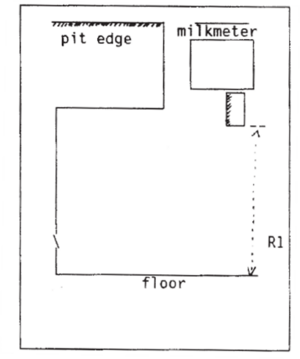
Figure 7. Installation of meter near the pit edge.
- Installation of the meter under the pit edge. In case it is not possible to install the meter near the pit edge, the meter can be installed under the pit edge according to the following conditions:
- Standards for the distances R1, R2 and R3 are as in figure 8.
- Sample-taking device needs to be easily accessible. No other equipment or pipes should be installed in front of the milk meter or the sample-taking device.
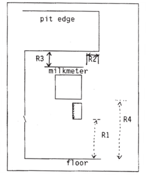
Figure 8. Installation of the meter under the pit edge.
- In all situations a good illumination of the milking parlour is recommended.


In-line milk analyser
The milk analyser shall:
- Give a value for fat and protein at a minimum, representative for all the milk collected during that milking session.
- Have no effect on the milk in any way.
A milk analyser shall be designed to permit easy reading and handling by the operator while it is attached to the milking equipment. In addition, it shall be resistant to all conditions encountered in its normal working environment (i.e. during milking, washing, disinfecting and, when applicable, transport). All parts subject to wear and tear shall be easily replaceable.
The conditions for assembling of milk analysers are given by the manufacturer of the device. If a milk analysers is fitted with a calibration device or calibration option, adequate precautions shall be taken to prevent unauthorized alteration of settings.
A milk analyser shall at least analyse fat and protein content, or as the total amount in that milking or as percentage of the milk. Other parameters as lactose, urea and somatic cells are not obliged, but could be a part of the certification test on request of the manufacturer. In the case of request for ICAR certification for additional components, these components have to fulfil the ICAR requirements in addition to fat and protein.
Note. Next to the parameters mentioned above, also parameters as for instance conductivity, blood and progesterone can be measured in milk. As for these parameters no accuracy limits are yet set, they are not a part of the requirements for milk recording devices. However, if these measures are a proxy for another component (i.e. conductivity measurements used to predict SCC), then the ICAR limits would apply.
Milk analysers can be used for different types of milk (cow, buffalo, goat, and sheep). The requirements are based on cow milk. For other species the milk analysers have to fulfil the same requirements until specific requirements are set per species.
Limits of error for milk yield and milk composition
The limits of error for both milk yield and fat percentage (in case of a milk recording device with sampling) are presented in Table 4 both for recording on the test day and daily recording of milk production. Moreover bias and standard deviation shall have a uniform distribution over the range of measured values using a test for homoscedasticity or heteroscedasticity. In case of daily recording of milk production, the milk production should be the average of at least 5 days.
| Table 5. Limits of error for milk yield and fat percentage per species for milk recording devices with a sampler
(both test day recording and daily recording). | ||||||
|---|---|---|---|---|---|---|
| Species | Milk yield | Fat percentage | ||||
| Range | Standard deviation1 | Bias2 | Range | Standard deviation | Bias | |
| Cattle | 2 - 10 kg | 0.50 kg | 0.2 kg | 2 – 8 % | 0.10 % fat | 0.05 % fat |
| > 10 kg | 5 % | 2 % | ||||
| Buffalo | 1 - 6 kg | 0.30 kg | 0.12 kg | 3 – 15 % | 0.30 % fat | 0.10 % fat |
| > 6 kg | 5 % | 2 % | ||||
| Goat | 0.3 - 0.8 kg | 0.04 kg | 0.025 kg | 2 – 12 % | 0.20 % fat | 0.10 % fat |
| > 0.8 kg | 5 % | 3 % | ||||
| Sheep | 0.3 - 0.8 kg | 0.04 kg | 0.025 kg | 2 – 12 % | 0.30 % fat | 0.10 % fat |
| > 0.8 kg | 5 % | 3 % | ||||
1In kg or in percentage of mean reference yield.
2In kg or in percentage of the reference yield.
In case of a milk recording device with a milk analyser, the requirements for milk yield as given in Table 4 apply also for these devices.
The requirements for milk composition are given in Table 5 for the compulsory elements fat and protein, and in Table 6, for the components which are not obliged. A test and potential certification for these components can be achieved on request of the manufacturer.
The requirements in Table 5 and Table 6 are based on the ICAR Guidelines for On-Farm Analysis (refer to Section 13 of the ICAR Guidelines).
| Table 6. The accuracy limits for on-farm milk analysers in milk recording for fat and protein
(compulsory elements for approval of milk analysers). | |||
|---|---|---|---|
| Accuracy | Range | St. Dev. | Bias |
| Fat | 2.0 - 6.0 g/100g | 0.25 g/100g | 0.13 g/100g |
| 5.0 - 14.0 g/100g | 0.25 g/100g | 0.25 g/100g | |
| Protein | 2.5 - 4.5 g/100g | 0.25 g/100g | 0.13 g/100g |
| 4.0 - 7.0 g/100g | 0.25 g/100g | 0.25 g/100g | |
| Table 7. The accuracy limits for on-farm milk analysers in milk recording for lactose,
urea and SCC (non-compulsory elements for approval of milk analysers). | |||
|---|---|---|---|
| Accuracy | Range | St. Dev. | Bias |
| Lactose | 4.0 – 7.0 g/100g | 0.25 g/100g | 0.13 g/100g |
| Urea | 10 – 70 mg/100g | 15.0 mg/100g | 3.0 mg/100g |
| SCC | 0-2000 | 25 % | 13 % |
Procedures for certification
Submission for testing
When a new milk recording device is to be submitted for a certification test (Procedure 1), the test applicant must provide to ICAR a list of devices with serial numbers, from which the required number of test devices can be randomly selected by the test centre assigned to conduct the test. The number of serial numbers and devices to choose from and to be chosen, differs per species and type of milk recording device, see Table 8 and Table 9.
| Table 8. Number of devices needed for a certification test. | |||
|---|---|---|---|
| Species | Cattle | Buffalo | Goat and/or sheep |
| Number on list with serial numbers | 50 | 30 | 30 |
| Number of devices for laboratory test | 2 | 2 | 2 |
| Number of devices for field test | 8 | 8 | 4 / species |
| Number of farms for the field test | 2 | 2 | 1 / species |
| Number of reserve devices | 1 (optional) | 1 (optional) | 1 (optional) |
In the case of milk recording devices with a milk analyser, from a list of 50 serial numbers, 2 devices will be chosen for the laboratory test and 6 devices for the field test, from which 4 devices will be installed in a milking parlour as described in Table 9.
| Table 9. Number of milk recording devices with milk analysers needed for a certification test. | |||
|---|---|---|---|
| Laboratory | Parlour | ||
| Number on list with serial numbers | 50 | 50 | |
| Number of devices for laboratory test | 2 | ||
| Number of devices for field test | 4 | ||
| Number of farms for the field test | 2 | ||
| Number of reserve devices | 1 (optional) | ||
In the case of permanently installed devices, they can be selected from already installed devices on two farms. In the case of milk recording devices intended for both goat and sheep, 4 devices shall be installed on a goat farm and 4 devices (all out of the same manufacturing lot), on a sheep farm.
The use of a reserve device is optional. In the case of a problem with a test device, the reserve meter can replace the faulty device. The test results of the reserve meter are excluded from the final analysis if not needed as a replacement.
Note: The manufacturer or test applicant is responsible for the correct installation and calibration of the devices in the laboratory and on the farms used for the field test. After installation, the test centre will conduct the tests without representatives of the manufacturer or test applicant present.
Modified devices and samplers
If previously-certified milk recording or sampling devices are modified in hardware and/or software, influencing the measurement or the testing routine, the manufacturer is responsible to report the modification(s) to the Chair of the Sub-Committee for Measuring, Recording and Sampling Devices (MRSD-SC). The Chair will consult the test centre responsible for the original certification test. Based on the information gathered by the Chair of the MRSD-SC, the manufacturer will be presented the plan of the required desk review or retest that must be completed to extend ICAR certification to the modified device or sampler.
The manufacturer reports the device or sampler modification to ICAR on the normal test application form and in case a desk review or retest is required, it is contractually managed by ICAR as done with other certification tests.
Certification test
The test of any new or modified recording and/or sampling device is based on the test plan developed by the assigned ICAR test centre. The test plan will identify the specifics of the test as applicable for the device.
The test plan may describe the following:
- Desk review for a modified device, sampler, or system,
- Laboratory test,
- Field test,
- Modified test that may include one or more of the above.
Test plans, while developed by the assigned ICAR test centre, are reviewed internally by all test centres to ensure complete and objective testing of the device and/or sampler. After internal review, the test plan is presented to the manufacturer/applicant and agreed upon by all parties.
Desk Review
As described in 2.2 of this procedure, if previously-certified milk recording or sampling devices are modified in the physical design, hardware and/or software that influences the milk measurement principle or sampling routine(s), these changes should be reported to ICAR. A desk review of the modification(s) shall be conducted as determined by the original test centre. The desk review will compare the original device, sampler or system and the reported modifications, referencing the original ICAR test and documentation provided the manufacturer/applicant.
The test centre will report to the MRSD-SC the findings of the desk review and may recommend extending ICAR-certification to the modified device, sampler or system or may recommend a modified test based on the findings.
Laboratory test
The objective of this test is to evaluate the device under several field conditions in order to assure that the device will give sufficient results.
Note: The test centre will determine, as stated in the test plan, if the laboratory test, either full or in part, is required for device, sampler or system under test.
A test rig is used, consisting of an artificial udder and a standard cluster (see ISO:6690), a pulsation system and a vacuum level and air inlet in the cluster which can be set to the test demands. In the laboratory test, the performance of the milk recording device is measured under different circumstances of flow rate, vacuum level, air bleed and tilting. In addition, the influence of the milk recording device on FFA and claw vacuum level may be recorded. Two devices shall be available for testing and depending on the test, one or both devices are used in the laboratory test.
Test solution
It is preferred that water, with an additive (salt or acid) to increase the conductivity as given by the manufacturer (mS/cm), is used instead of milk. However, depending on the measuring principle, it can be necessary to use fresh milk or artificial milk, as indicated by the manufacturer. In case of artificial milk the manufacturer is obliged to provide the artificial milk. In case water or artificial milk is used and the measurement principle of the milk meter is volumetric, a compensation for density should be calculated, based on the assumed density of milk of 1.030 for cows, 1.032 for goat and 1.036 for buffalos and sheep. For reference quantity the fluid is weighed with an accuracy of 0.01 kg for cattle and buffalo and 0.005 kg for goat and sheep.
For a number of tests (i.e. influence of free fatty acids) the use of fresh milk, direct from a milking installation, is necessary. The milk shall be kept on a temperature of 30±2°C until used in the tests. The milk shall be of healthy animals and shall have a normal composition.
Reference meters and flow rates
Some tests of the milk recording meters have to be done by comparing results with reference meters and flow rates. A reference milking unit shall be used when testing the influence of a milk meter on teat end vacuum. Reference flow rates are used to describe the function at different levels. A reference milk meter shall be used also to test the milk meter influence on free fatty acids (FFA) in the milk.
The reference milking unit for dairy cattle, buffalo, sheep and goats should be representative of those widely used in a large number of countries.
Water flow rates
The reference value is 5.0 kg/min.
Air flow rates
The reference value is 12.0 l/min for cattle and buffalo and 8.0 l/min for goats and sheep. See IDF publication IDF small ruminants.
Reference meter for cattle and buffalo
When testing the milk meter influence on free fatty acids (FFA), the Tru Test HI model with 13 mm inlet and outlet shall be used as reference milk meter.
Reference meter for goats and sheep
There is no reference milk meter.
Test conditions
The minimum time per test shall be at least 2 minutes for each flow rate. The device is tested at the vacuum level recommended by the manufacturer or, when no vacuum level is recommended, by the intermediate vacuum level used in the test for influence of vacuum level (40 kPa for cattle and buffalo, 38 kPa for sheep and goat). A tolerance in the vacuum level of ±0.5 kPa is acceptable. The air bleed in the cluster shall be 10 l free air/min for cattle and buffalo and 6 l free air/min for goat and sheep.
The device shall be mounted in a height relative to the cluster as is recommended by the manufacturer. The outlet of the milk recording device to the bucket or jar, used for reference, shall be mounted comparable to field circumstances. In any case blockage of the outlet must be avoided.
The following tests are performed as part of the laboratory test:
Influence of flow rate on accuracy and sampling
Both devices are tested, with at least 20 measurements per device and, at least 3 measurements per flow rate. The different flow rates for testing are depending on species (see Table 10).
| Table 10. Flow rates to be tested. | |
|---|---|
| Species | Flow rate (kg/min) |
| Cattle | 1.0, 2.0, 3.0, 6.0, 9.0 and 12.0 |
| Buffalo | 0.3, 0.6, 1.2, 2.5, 4.0 and 6.0 |
| Goat and sheep | 0.3, 0.6, 1.2, 2.0, 3.0 and 5.0 |
Deviation (milk meter - reference, milk analyser - reference) and/or sample percentage are plotted against flow rate. The milk meter should work properly for flow rates up to 9.0 kg for cattle, 4.0 kg/min for buffalo and 3.0 kg for goat and sheep; at higher flow rates the meter should still work. Properly in this regard means that repeatability and correlation are such that the device will give sufficient results under field conditions.
Influence of vacuum level on accuracy and sampling
One device is tested using the flow rates and number of repetitions noted above in the ‘influence of flow rate on accuracy and sampling’ at different vacuum levels depending on species:
| Table 11. Vacuum levels to be tested. | ||
|---|---|---|
| Species | Vacuum level (kPa) | |
| Cattle and buffalo | 30, 40 and 50 | |
| Goat and sheep | 30, 38 and 45 | |
Deviation (milk meter - reference) and sample percentage shall be plotted against flow rate and vacuum level.
Influence of air bleed
One device is tested at one of the vacuum levels with different air bleeds and a flow rate depending on species (See Table 12).
| Table 12. Flow rate and air bleeds to be tested for influence of air bleed. | ||
|---|---|---|
| Species | Flow rate (kg/min) | Air bleeds (l free air/min) |
| Cattle | 5 | 0, 4, 12, 20, 30 |
| Buffalo | 2.5 | 0, 4, 12, 20, 30 |
| Goat and sheep | 2 | 0, 4, 8, 16, 30 |
Per air bleed, at least 3 repetitions should be made. The deviation (milk meter - reference) and/or sample percentage shall be plotted against air bleed.
Influence of tilting the device
One device is tested at the recommended vacuum level and standard air bleed at a flow rate depending on species and at inclinations as mentioned in Table 13.
| Table 13. Flow rate and inclination to be tested for influence of tilting. | ||
|---|---|---|
| Species | Flow rate (kg/min) | Positions |
| Cattle | 5 | Horizontal, 5 degrees to left, right, front and back |
| Buffalo | 2.5 | Horizontal, 5 degrees to left, right, front and back |
| Goat and sheep | 2 | Horizontal, 5 degrees to left, right, front and back |
Per position, at least 3 repetitions should be made. The deviation (milk meter – reference), and sample percentage shall be plotted against position.
Effect of the milk recording device on teat end vacuum
Milk recording devices shall meet the standards described in ISO:5707. The devices shall be tested by comparing the vacuum in the cluster with and without the milk recording device according to ISO:5707 and ISO:6690. However, if the manufacturer specifies a particular type of cluster assembly for use with the milk meter, then that type shall be used.
Effects on milking and milk quality
A milk recording device including a sampler or milk analyser shall:
a. Have no, or a limited effect, on the teat end vacuum as stated in ISO:5707 and measured according ISO:6690.
b. Have no, or a limited effect, on Free Fatty Acids (FFA) in the milk, measured according to IDF N° 265/1991 - Determination of free fatty acids in milk and milk products. The effect of the milk recording device on FFA shall not be more than the effect of a reference milk recording device;
c. Have no, or a limited effect, on the bacteriological quality of the milk. The milk recording device shall not accumulate milk soil or bacteria, when using the cleaning procedure described by the manufacturer.
Evaluation of method for routine calibration test
The method of routine calibration testing, as given by the manufacturer, will be tested on two milk meters including the milk analysers when appropriate and evaluated for use in the field. More details on the ICAR guidelines for installation and routine calibration tests may be found in Procedure 6.
Evaluation of cleaning properties of the milk recording device
A technical evaluation of the cleaning properties of the milk recording device will be performed. The evaluation shall give information about:
- Design of the internal and external parts of the device (e.g. lack of dead ends, unreachable parts for cleaning fluid etc.).
- Sufficient turbulence during cleaning of the milk recording device (device in cleaning mode).
- Special needs for cleaning (e.g. extra cleaning fluid).
Evaluation of carry-over in the milk recording device and sampler
A technical evaluation of the carry-over potential of the milk recording and sampling device will be performed.
Field test
Field tests have to be carried out to assess the performance of the milk recording device under field conditions. These tests are to be carried out under normal milking conditions on farms with, for the breed and country, representative level of production and a normal distribution of milk quantities, flow rates and fat percentages.
It is known that milking machine characteristics and milk flow rate have major effects on the accuracy of milk recording devices with samplers and milk analysers. The milking installations on the farms where the tests are conducted have to comply with ISO:5707.
Test procedure
Milk quantity given by the milk meters is compared with the milk quantity of the reference. For reference the whole amount of milk produced during the milking of a given animal is collected in a suitable bucket and the weight of that milk is measured using a scale with an accuracy of +0.02 kg for cows and buffalos and +0.01 kg for goat and sheep. The amount of reference milk is corrected for the amount (weight) of the sample taken for reference analysis of fat percentage.
Duplicate samples are taken from the milk collected in the bucket (reference) and duplicate samples are taken from the milk collected by the sampler. In all cases, milk in the bucket and sampler has to be mixed thoroughly before taken samples. For any observation where no duplicate sample is available (it is not possible to take two samples), this sample should be analysed twice if possible and the results will be treated as duplicates. Samples are analysed for fat percentage by an accredited laboratory as identified in the test plan.
In case of a milk analyser test, results are compared with the reference samples.
As flow rate could influence the accuracy for yield, sampling and milk components, it is advised to record average and maximum flow rate of each milking (or at least machine on time). These data could be used in the statistical analyses and the results could replace a part of the laboratory test.
In each test run, at least 40 readings per device have to be done. If necessary, such a farm test may take one or more consecutive days. Valid readings have minimum and maximum values for quantity and fat percentage, depending on species, as specified in Table 14.
| Table 14. Valid reading in the field test per species (minimum and maximum). | |||
|---|---|---|---|
| Species | Milk production
(reference) |
Fat percentage
(reference) |
Protein percentage
(reference)a |
| Cattle | 2 - 40 kg | 2 - 8 % | 2.5 - 5 % |
| Buffalo | 1 - 15 kg | 3 - 15 % | 3 - 8 % |
| Goat | 0.3 - 6 kg | 2 - 12 % | 2 - 7 % |
| Sheep | 0.3 - 6 kg | 2 - 12 % | 3 - 8 % |
aProtein content is only needed for milk analysers.
Cleaning and disinfection
Tests of effectiveness of cleaning and disinfecting of the milk recording devices shall be carried out during the farm tests on all the devices under test by a visual inspection. In case of residues found, additional information shall be gathered from bulk milk quality and/or ATP measurements. With the ATP method, swabs will be taken on parts of the device where cleaning and disinfecting could be ineffective (or less effective than expected), e.g. on the top of the meter, in different chambers, in samplers or tubes.
The milk meter has passed the test if:
- There are no visible residues on milk contact surfaces.
- Bulk milk quality and/or ATP show no raise in number of bacteria/ATP levels.
Faulty device in test
In case one milk recording device fails due to poor calibration or technical defect where the other devices pass the test, then:
- The test centre may decide to replace the faulty device with the reserve device and have it installed and tested, or
- The test centre may ask the manufacturer to repair and/or calibrate the device and then retest that device.
In the report to ICAR it will be stated which milk recording device is replaced or retested and why.
Effects on milking or milk quality
When the laboratory test is omitted, additional samples or measurements related to the effect of the recording or sampling device may be taken during the field test.
- Vacuum drops caused by the milk meter and/or sampler may be measured during milking using special vacuum measuring devices. In addition, the flow milk flow rate may also be measured. The recording or sampling device shall not have, or a limited effect, on the teat end vacuum as stated in ISO:5707 and measured according ISO:6690. When the deviations are higher than expected, a laboratory test is the most appropriate way to evaluate the effect.
- Have no, or a limited effect, on Free Fatty Acids (FFA) in the milk, measured according to IDF N° 265/1991 - Determination of free fatty acids in milk and milk products. Bulk milk samples may be taken during the field test and compared with historical data. The effect of the milk recording device on FFA shall not be more than the effect of a reference milk recording device;
Handling and operation
In case relevant handling or operational problems occur in the first test run, the manufacturer shall be informed and allowed to solve the problem before the second run, without in any way affecting the accuracy of the milk recording device. Any remarks about handling and operation of the milk recording device in the field, made by the people involved in testing (including the farmers), should be noted in the report, also the problems which are solved during the test period.
Analysis (statistical)
A software program performing the statistical analysis, graphics and conclusions is available for each species. The software is owned by ICAR and has been made available to the ICAR test centres and associate members of ICAR.
All milk recording devices in test must fulfil both the standards for bias and standard deviation of accuracy for milk yield and fat content (See table 2). If the reference values for yield or fat percentage are outside the limits for valid readings (Table 6), these readings for yield or fat percentage will not be used in the analyses. If the values of duplicate samples for fat percentage differ with more than 0.10% these readings should be omitted. The average of the duplicates of the reference and of the milk recording device is calculated and used in the analyses.
The difference between the reference and the milk recording device is calculated for yield and for fat percentage and the difference is compared with the reference value. Even the extreme results for differences between reference and milk recording device should be used in calculations, unless there is a reason to assume an error has been made or the milk recording device has been broken. There shall be no fewer than 35 readings left for one milk recording device for both yield and fat percentage; otherwise a retest of that milk recording device will be necessary.
Statistical treatment is done to find out if outlier data exist in the remaining data and in what way the data may modify the assessment of the bias related to the milk recording device. The standards for bias should be fulfilled both with and without outlier data. The standards for reproducibility should be fulfilled with all data.
Both bias and reproducibility are also tested for homoscedasticity. There is homoscedasticity if the residuals of the regression of the differences between milk recording device yields and reference yields on these reference yields are identically and independently distributed. Homoscedasticity is tested by a X2 test that compares the matrix of variance covariance of the estimators of the coefficients of regression obtained under the assumption of heteroscedasticity, with the same matrix obtained under the assumption of homoscedasticity.
First, homoscedasticity of the residuals of the regression is tested. If there is homoscedasticity of the residuals, the current rule concerning calculation of the standard deviation of reproducibility and the conditions of acceptability of a milk recording device are maintained.
If homoscedasticity is not proven by the specific test it means that there is heteroscedasticity. Then the variance of residuals is not similar according to different classes of results and test of the standard deviation of reproducibility is done per class of reference yield for each milk recording device. Classes for yield and fat content are depending on the species. In each class a standard deviation of reproducibility is calculated and compared to a threshold value that depends on the average of the reference yields for the class. For each class the current procedure done for all data is applied. If the standard deviation of reproducibility according to ICAR's requirements fails for one (or more) class, the milk recording device is rejected. The minimum number of measurements for a class of reference yield is fixed as 10. The statistical analysis is also described in the flow chart in Figure 9.
Milk yield
Estimate the correlation between these differences and the reference yields.
If the correlation is not significant (P>0.05), it is assumed that the bias of the milk recording device is independent of the yield. Use the mean difference between the reference and milk recording device yields as the bias of the milk recording device, and use the standard deviation of the differences as the reproducibility of the milk recording device.
If the correlation is significant (P<0.05), it is assumed that the bias of the milk recording device is dependent on the yield. Calculate the regression of the differences on the reference yields, and use the residual standard deviation about the regression line as the reproducibility of the milk recording device.
In both instances, plot the observed differences, the expected bias and the maximum acceptable bias against yield. If the expected bias falls outside the acceptable limits at any point within the range of observed reference yield the milk recording device is rejected.
Fat percentage (valid for testing samplers)
Estimate the correlation between the difference and reference.
If the correlation is not significant (P>0.05), it is assumed that the bias of the milk recording device is independent of the fat content of the milk. Use the mean difference between the reference and milk recording device samples as the bias of the milk recording device. Use the standard deviation of the differences between the means for the reference samples and the means for the milk recording device samples as an estimate of the accuracy of the milk recording device.
If the correlation is significant (P<0.05), it is assumed that the bias of the milk recording device is dependent on the fat content of the milk. Calculate the regression of the differences between reference samples and milk recording device samples on the overall mean fat content at each observation, and use the residual standard deviation about the regression line as an estimate of reproducibility of the milk recording device.
In both instances, plot the observed differences, the expected bias and the maximum acceptable bias against the overall mean fat content for each observation. If the expected bias lies outside the acceptable limits at any point within the range of observed fat contents the milk recording device is rejected.
Milk components (valid for milk analysers only)
For all milk components in the approval test of a milk analyser, the data will be analysed according to the procedure described in “Guidelines on on-farm milk analyses”.
Remark: in contrast to the 'Guidelines on on-farm milk analyses' the number of farms and readings do differ. Instead of 5 farms and 100 readings, in the procedure described in this document 2 farms (1 automatic milking system, 1 milking parlour) are used with respectively 2 and 4 devices. For each device, 40 valid readings are needed, as is usual for testing the accuracy for yield. So, in total 240 readings will be used for analyses on milk components.
Procedure 5 : Procedure for Testing of Automatic Milk Recording and Sampling Systems
Requirements for automatic milk recording and sampling systems
Automatic milk recording systems record milk yield and a) take samples of milk or b) perform milk analysis without human supervision or interference. Automatic sampling systems are well-known in automatic milking systems, but could also be used in milking parlours. Systems for automatic milk recording shall:
- Deliver electronic data. The file must include cow ID, amount of milk, time of milking and the position where the cow was milked. The file must contain every milking during the recording period.
- Have no mismatches of animal identification with milking time, milk production and sample identification/results of the milk analyser.
- Have a success rate in reading animal identification of at least 98 % (and must have the technical capability of 100% correct identification at recording).
- Indicate if a milking is a complete milking (at least 80 % of the expected milk yield is collected).
- Take samples each time an animal is milked and take care that samples are properly treated and/or stored to ensure the quality of the sample for analyses or perform milk analysis each time an animal is milked.
- Have a capacity to record and sample all the animal milkings within the intended sampling period;
- Have a rate of sampling / milk analysing to ensure no or minimal delay of the milking of the next animal.
- In case of sampling: the sampling unit shall meet with ergonomic demands (weight, construction, connectivity, accessibility of critical places, portability).
Note: ICAR certification for automatic milk recording and sampling systems are based on the combination of the robot and the sampler. The automatic milk recording system must be tested with automatic sampling device(s) to achieve an ICAR certification. The automatic milk recording system cannot be tested by itself for milk yield nor may an automatic sampling device be tested by itself for milk sampling.
Note: Multiple automatic milk samplers may be tested with a single automatic milk recording system and multiple versions of the automatic milk recording system may be tested with one or more automatic milk samplers as part of the same test when requested as part of the application process.
- For the purposes of official milk recording, only devices are valid which meet the definitions of ISO:3918.
- Milk recording devices are to be designed to operate under the normal conditions of machine milking as defined in ISO:5707 and ISO:20966.
- Materials used in the manufacturing of milk recording devices must comply with the requirements of ISO: 5707 and ISO:20966 and the legal provisions in the country of a member organization.
- Manufacturers shall specify the precise conditions under which a recording device is designed to operate properly within the scope of the ICAR guidelines and provide written operating instructions.
The combination of the automatic milk recording system and sampler combination should have a measuring and sampling capacity for a milk yield of at least:
- 40 kg for cattle.
- 15 kg for buffalo.
- 6 kg for goats.
- 3 kg for sheep.
Yield display
As automatic milking systems are connected to a computer system, and this system is used for official milk recording, a print or electronic file must be available.
The file must include:
- cow ID,
- amount of milk,
- time of milking,
- the position where the cow was milked.
The printout or file must contain every milking on recording day. In case a display is used, it shall consist of easily legible figures at least 5 mm in height, which can be read at any level of ambient light.
The display shall indicate the milk yield in kilograms with increments of no more than 0.2 kg, with the preference of increments of 0.1 kg.
Sampling
The sample shall be:
- Representative for all the milk collected during that milking.
- Sufficient amount for analysing the milk composition.
A minimum volume of 25 ml shall be taken at the minimum recordable milk yield of 5 kg for cattle.
Note. The sufficient amount for analysing is depending on the country and varies between 25 ml and 50 ml. In the case when multiple samples of multiple milking are combined, 25 ml sample per milking is sufficient in all countries. When samples from milkings are separately analysed, in some countries a higher amount of sample may be prescribed.
The sampler shall be easily accessible, sampling tubes or bottles (when used) shall be easy to place and remove.
Where milk sampling is done by a remote sampling device, then it shall be designed and constructed so that:
- The operational conditions must comply with all local, regional and national health and safety requirements where applicable
- It may be included in the automatic milking system washing circuit.
- Carry-over of milk between animals is minimized.
In-line milk analyser in automatic milk recording systems
In the case that the automatic milk recording systems is equipped with an in-line milk analyser, the milk analyser shall:
- Give a value for fat and protein at a minimum, representative for all the milk collected during that milking session.
- Have no observed or measured effect on the milk flow or quality in any way.
A milk analyser shall be resistant to all conditions encountered in its normal working environment (i.e. during milking, washing, disinfecting and, when applicable, transport). All parts subject to wear and tear shall be easily replaceable.
The conditions for assembling of milk analysers are given by the manufacturer of the device. If a milk analysers is fitted with a calibration device or calibration option, adequate precautions shall be taken to prevent unauthorized alteration of settings.
A milk analyser shall at least analyse fat and protein content, or as the total amount in that milking or as percentage of the milk. Other parameters as lactose, urea and somatic cells are not obliged, but could be a part of the certification test on request of the manufacturer. In the case of request for ICAR certification for additional components, these components have to fulfil the ICAR requirements in addition to fat and protein.
Note. Next to the parameters mentioned above, other parameters such as conductivity, blood and progesterone may be measured in milk. As for these parameters, no accuracy limits are yet defined, they are not a part of the requirements for milk recording devices. However, if these measures are a proxy for another component (i.e. conductivity measurements used to predict SCC), then the ICAR limits for such parameters would apply.
Limits of error for milk yield and milk composition
The limits of error for both milk yield and fat percentage are presented in Table 15 both for recording on the test day and for daily recording of milk production. Moreover, bias and standard deviation shall have a uniform distribution over the range of measured values using a test for homoscedasticity or heteroscedasticity. In case of daily recording of milk production, the milk production should be the average of at least 5 days.
| Table 15. Limits of error for milk yield and fat percentage per species for milk recording devices
with a sampler (both test day recording and daily recording). | ||||||
|---|---|---|---|---|---|---|
| Species | Milk yield | Fat percentage | ||||
| Range | Standard deviation1 | Bias2 | Range | Standard deviation | Bias | |
| Cattle | 2 - 10 kg | 0.50 kg | 0.2 kg | 2 – 8 % | 0.10 % fat | 0.05 % fat |
| > 10 kg | 5 % | 2 % | ||||
1In kg or in percentage of mean reference yield.
2In kg or in percentage of the reference yield.
In case of an automatic milk recording device with an in-line milk analyser, the requirements for milk yield as given in Table 15 apply also for these devices.
The requirements for milk composition are given in Table 16 for the compulsory elements fat and protein, and in Table 17, for the components, which are not obliged. A test and potential certification for these components can be achieved on request of the manufacturer.
The requirements in Table 16 and Table 17 are based on the ICAR Guidelines for On-Farm Analysis (refer to Section 13 of the ICAR Guidelines).
| Table 16. The accuracy limits for on-farm milk analysers in milk recording for fat and protein
(compulsory elements for approval of milk analysers). | |||
|---|---|---|---|
| Accuracy | Range | St. Dev. | Bias |
| Fat | 2.0 - 6.0 g/100g | 0.25 g/100g | 0.13 g/100g |
| 5.0 - 14.0 g/100g | 0.25 g/100g | 0.25 g/100g | |
| Protein | 2.5 - 4.5 g/100g | 0.25 g/100g | 0.13 g/100g |
| 4.0 - 7.0 g/100g | 0.25 g/100g | 0.25 g/100g | |
| Table 17. The accuracy limits for on-farm milk analysers in milk recording for lactose,
urea and SCC (non-compulsory elements for approval of milk analysers). | |||
|---|---|---|---|
| Accuracy | Range | St. Dev. | Bias |
| Lactose | 4.0 – 7.0 g/100g | 0.25 g/100g | 0.13 g/100g |
| Urea | 10 – 70 mg/100g | 15.0 mg/100 g | 3.0 mg/100 g |
| SCC (x1000) | 0-2000 | 25 % | 13 % |
Procedures for certification
Submission for testing
When a new automatic milk recording system is to be submitted for a certification test (Procedure 1), the test applicant must provide to ICAR a list of potential farms with the system in operation to select for the test.
| Table 18. Number of automatic milk recording systems with either automatic
milk samplers or milk analysers needed for a certification test. | ||
|---|---|---|
| Robot | ||
| Number of AMS for field test | 2 | |
| Number of farms for the field test | 2 | |
| Number of reserve devices | NA | |
Note: The manufacturer/test applicant is responsible for the correct installation and calibration of the automatic milk recording system(s) on the farms. After installation, the test centre will conduct the tests without representatives of the manufacturer/test applicant present.
Automatic milk recording systems
An automatic milk recording system is a combination of automatic recording of milk production and automatic sampling / automatic milk analyses. In most cases, the recording of milk production and automatic milk analyses is performed on daily basis and the automatic sampling is performed on the test day only. In case the automatic sampling system is combined with more types of milking systems and/or more types of milk meters, each combination has to be tested for approval.
The test procedure for certification of milk recording devices is adjusted to the situation with automatic milk recording systems on the following points:
- In case the milk meter used in automatic milk recording is of an already approved type, the laboratory test is omitted.
- The test will be carried out by testing two out of a series of at least 10 milk recording/sampling devices. Both devices should be tested in two milk recorded herds. The farms will be chosen by the ICAR test centre from a list of farms given by the manufacturer/test applicant or dealer. A test farm, operated and/or owned by the manufacturer, is not eligible as a farm for the ICAR test.
- In the case of automatic (voluntary) milking systems, the device tests will be carried out as part of the normal daily milking routine of the chosen farms.
- For each test herd, at least 50 valid recordings will be taken (milk yield + samples) from no less than 40 animals.
- All readings will be checked for correct identification and combination of animal identification, milking time and milk production.
- The test will check that correct identification of sample bottles can be maintained even in case the sampling procedure fails due to mechanical or software problems.
- The manufacturer/test applicant provides the test centre with a user manual of the sampling device and gives instructions about handling of the sampling system (connection with the milking system, power-supply, tubes etc.). This user manual will be an integral part of the ICAR test. Following the user manual, the test centre connects the sampling system to the milking system and carries out the test procedure. The user manual must also give instructions to check the correct functionality of the sampling device.
Modified automatic milk recording or sampling systems
If previously certified automatic milk recording or sampling devices in a system are modified in hardware and/or software, influencing the measurement or the testing routine, the manufacturer is responsible to report the modification(s) to the Chair of the Sub-Committee for Measuring, Recording and Sampling Devices (MRSD-SC). The Chair will consult the test centre responsible for the original certification test. Based on the information gathered by the Chair of the MRSD-SC, the manufacturer will be presented the plan of the required desk review or retest that must be completed to extend ICAR certification to the modified device or sampler.
The manufacturer reports the device or sampler modification to ICAR on the normal test application form.
Certification test
The test of any new or modified automatic milk recording and/or sampling device is based on the test plan developed by the assigned ICAR test centre. The test plan will identify the specifics of the test as applicable for the device.
The test plan may describe the following:
- Desk review for a modified recording device, sampler, or combination,
- Field test,
- Modified test that may include one or more of the above.
Test plans, while developed by the assigned ICAR test centre, are reviewed internally by all test centres to ensure complete and objective testing of the automatic milk recording and sampling system. After internal review, the test plan is presented to the manufacturer or applicant and agreed upon by all parties.
Desk Review
As described in 5.2.3 of this procedure, if previously-certified milk recording or sampling devices are modified in hardware and/or software, influencing the measurement, sampling or the testing routine, a desk review of the modification(s) may be conducted as determined by the original test centre. A desk review will compare the original device, sampler or system and the reported modifications, referencing the original ICAR test and documentation provided by the manufacturer/applicant.
The test centre will report to the MRSD-SC the findings of the desk review and may recommend extending ICAR-certification to the modified device, sampler or system or may recommend a modified test based on the findings.
Field test
Field tests have to be carried out to assess the performance of the automatic milk recording and sampling system under field conditions. These tests are to be carried out under normal milking conditions on farms with, for the breed and country, representative levels of production and a normal distribution of milk quantities, flow rates and fat percentages.
It is known that milking machine characteristics and milk flow rate have major effects on the accuracy of milk recording devices with samplers and milk analysers. The milking installations on the farms where the tests are conducted have to comply with ISO:5707.
For a number of tests (i.e. influence of free fatty acids) the use of fresh milk, direct from a milking installation, is necessary. The milk shall be kept on a temperature of 30±2°C until used in the tests. The milk shall be of healthy animals and shall have a normal composition.
Test procedure
Milk quantity given by the milk meters is compared with the milk quantity of the reference. For reference, the whole amount of milk produced during the milking of a given animal is collected in a suitable bucket and the weight of that milk is measured using a scale with an accuracy of +0.02 kg. The amount of reference milk is corrected for the amount (weight) of the sample taken for reference analysis of fat percentage.
Duplicate samples are taken from the milk collected in the bucket (reference) and duplicate samples are taken from the milk collected by the automatic milk sampler. In all cases, milk in the bucket and sampler has to be mixed thoroughly before taken samples. For any observation where no duplicate sample is available (it is not possible to take two samples), this sample should be analysed twice if possible and the results will be treated as duplicates. Samples are analysed for fat percentage by an accredited laboratory as identified in the test plan.
In case of a milk analyser test, results are compared with the reference samples.
As flow rate could influence the accuracy for yield, sampling and milk components, it is advised to record average and maximum flow rate of each milking (or at least machine on time).
In each test run at least 40 readings per device have to be done. If necessary, such a farm test may take one or more consecutive days. Valid readings have minimum and maximum values for quantity and fat percentage, depending on species, as specified in Table 19.
| Table 19. Valid reading in the field test per species (minimum and maximum). | |||
|---|---|---|---|
| Species | Milk production
(reference) |
Fat percentage
(reference) |
Protein percentage
(reference)a |
| Cattle | 2 - 40 kg | 2 - 8 % | 2.5 - 5 % |
aProtein content is only needed for milk analysers.
Cleaning and disinfection
Tests of effectiveness of cleaning and disinfecting of the milk recording devices shall be carried out during the farm tests on all the devices under test by a visual inspection. In case of residues found, additional information shall be gathered from bulk milk quality and/or ATP measurements. With the ATP method, swabs will be taken on parts of the device where cleaning and disinfecting could be ineffective (or less effective than expected), e.g. on the top of the meter, in different chambers, in samplers or tubes.
The automatic milk recording and sampling system has passed the test if:
- There are no visible residues on milk contact surfaces.
- Bulk milk quality and/or ATP show no raise in number of bacteria/ATP levels.
Faulty automatic milk recording device or sampler in the test
In case that the automatic milk recording system fails due to poor calibration or technical defect, then:
- The test centre may decide to select a different farm from the list provided by the manufacturer.
- The test centre may stop the test, ask the manufacturer to repair and/or calibrate the device, and then retest the combination of the automatic milk recording device and sampler.
In case that the automatic milk sampler fails due to poor operation or technical defect, then:
- The test centre may decide to select a different automatic milk sampler of the same model, when available to use, for the test with automatic milk recording system,
- The test centre may stop the test, ask the manufacturer to repair and/or calibrate the sampler, and then retest with that sampler.
Analysis (statistical)
A software program performing the statistical analysis, graphics and conclusions is available for each species. The software is owned by ICAR and has been made available to the ICAR test centres and associate members of ICAR.
All milk recording devices in test must fulfil both the standards for bias and standard deviation of accuracy for milk yield and fat content (See table 2). If the reference values for yield or fat percentage are outside the limits for valid readings (Table 6), these readings for yield or fat percentage will not be used in the analyses. If the values of duplicate samples for fat percentage differ with more than 0.10% these readings should be omitted. The average of the duplicates of the reference and of the milk recording device is calculated and used in the analyses.
The difference between the reference and the milk recording device is calculated for yield and for fat percentage and the difference is compared with the reference value. Even the extreme results for differences between reference and milk recording device should be used in calculations, unless there is a reason to assume an error has been made or the milk recording device has been broken. There shall be no fewer than 35 readings left for one milk recording device for both yield and fat percentage; otherwise, a retest of that milk recording device will be necessary.
Statistical treatment is done to find out if outlier data exist in the remaining data and in what way the data may modify the assessment of the bias related to the milk recording device. The standards for bias should be fulfilled both with and without outlier data. The standards for reproducibility should be fulfilled with all data.
Both bias and reproducibility are also tested for homoscedasticity. There is homoscedasticity if the residuals of the regression of the differences between milk recording device yields and reference yields on these reference yields are identically and independently distributed. Homoscedasticity is tested by a X2 test that compares the matrix of variance covariance of the estimators of the coefficients of regression obtained under the assumption of heteroscedasticity, with the same matrix obtained under the assumption of homoscedasticity.
First, homoscedasticity of the residuals of the regression is tested. If there is homoscedasticity of the residuals, the current rule concerning calculation of the standard deviation of reproducibility and the conditions of acceptability of a milk recording device are maintained.
If homoscedasticity is not proven by the specific test, it means that there is heteroscedasticity. Then the variance of residuals is not similar according to different classes of results and test of the standard deviation of reproducibility is done per class of reference yield for each milk recording device. Classes for yield and fat content are depending on the species. In each class, a standard deviation of reproducibility is calculated and compared to a threshold value that depends on the average of the reference yields for the class. For each class the current procedure done for all data is applied. If the standard deviation of reproducibility according to ICAR's requirements fails for one (or more) class, the milk recording device is rejected. The minimum number of measurements for a class of reference yield is fixed as 10. The statistical analysis is also described in the flow chart in Figure 10.

Milk yield
Estimate the correlation between these differences and the reference yields.
If the correlation is not significant (P>0.05), it is assumed that the bias of the milk recording device is independent of the yield. Use the mean difference between the reference and milk recording device yields as the bias of the milk recording device, and use the standard deviation of the differences as the reproducibility of the milk recording device.
If the correlation is significant (P<0.05), it is assumed that the bias of the milk recording device is dependent on the yield. Calculate the regression of the differences on the reference yields, and use the residual standard deviation about the regression line as the reproducibility of the milk recording device.
In both instances, plot the observed differences, the expected bias and the maximum acceptable bias against yield. If the expected bias falls outside the acceptable limits at any point within the range of observed reference yield the milk recording device is rejected.
Fat percentage (valid for testing samplers)
Estimate the correlation between the difference and reference.
If the correlation is not significant (P>0.05), it is assumed that the bias of the milk recording device is independent of the fat content of the milk. Use the mean difference between the reference and milk recording device samples as the bias of the milk recording device. Use the standard deviation of the differences between the means for the reference samples and the means for the milk recording device samples as an estimate of the accuracy of the milk recording device.
If the correlation is significant (P<0.05), it is assumed that the bias of the milk recording device is dependent on the fat content of the milk. Calculate the regression of the differences between reference samples and milk recording device samples on the overall mean fat content at each observation, and use the residual standard deviation about the regression line as an estimate of reproducibility of the milk recording device.
In both instances, plot the observed differences, the expected bias and the maximum acceptable bias against the overall mean fat content for each observation. If the expected bias lies outside the acceptable limits at any point within the range of observed fat contents the milk recording device is rejected.
Milk components (valid for milk analysers only)
For all milk components in the approval test of a milk analyser, the data will be analysed according to the procedure described in “Guidelines on on-farm milk analyses”.
Remark: In contrast to the 'Guidelines on on-farm milk analyses’, the number of farms and readings do differ. Instead of 5 farms and 100 readings, in the procedure described in this document 2 farms (1 automatic milking system, 1 milking parlour) are used with respectively 2 and 4 devices. For each device, 40 valid readings are needed, as is usual for testing the accuracy for yield. So, in total 240 readings will be used for analyses on milk components.
Procedure 6: Evaluation of Installation and Routine Calibration Procedures for Recording and Sampling Devices
Installation test
Note: All platform scales, balance beams and spring scales used as reference during installation and routine calibration tests must be of adequate range of weighing and must be calibrated at the beginning of a test. The accuracy of platform scales, balance beams and spring scales should be at least within 0.02 kg.
After installing milk recording devices in a new parlour or an extended parlour, the performance of the device must be tested by means of an installation test. This test is carried out in agreement with the member organization and/or in collaboration with the technician of the manufacturer or an authorized dealer. The manufacturer or the dealer is responsible for the installation, calibration and testing of the measuring or recording devices before the acceptance test is carried out.
An installation test for a milk recording device consists of a milking test and/or, depending on the requirements for calibration testing, a parameter check for the calibration as provided by the manufacturer and evaluated during the ICAR test of the device. For measuring or recording devices providing estimates of parameters other than milk yields, the installation test consists of the procedure provided by the manufacturer and evaluated during the ICAR test of the device.
Only when results of the installation test are within the limits for the test, the device may be used for official recording.
Milking installation test for milk recording devices
The milking installation test for milk recording devices must follow the following steps to be valid.
Step 1
Record three test observations with the milk meter and the reference and calculate the difference between the milk meter and the reference. The calibration of the milk meter is considered correct if the average difference is less than or equal to 150 % of the limits for bias according to Table 2. Limits of error for milk yield and fat percentage per species for milk recording devices with a sampler in Procedure 4 of Section 11.
The average difference of all the devices on the farm shall be less than or equal to 100% of the limits for bias according to Table 2. Limits of error for milk yield and fat percentage per species for milk recording devices with a sampler in Procedure 4 of Section 11.
Step 2
If the difference exceeds the test limits, the milk recording device(s) involved shall be recalibrated and three new readings per device shall be completed. The calculation and checking mentioned in step 1 shall be repeated.
Step 3
If the difference is still larger than 150% of the limits, an additional three more readings shall be completed, and the average difference of six readings will be calculated. The calibration of the milk meter is considered correct if the average difference is less than or equal to 150% of the limits for bias according to Table 2. Limits of error for milk yield and fat percentage per species for milk recording devices with a sampler in Procedure 4 of Section 11.
If the average difference does not meet these limits, the milk meter is not acceptable. Readjustment, repair or replacement must be done by the manufacturer, after which the above procedure must be repeated.
Note: In some situations the milk recording device needs more than three observations for a correct milking test. In this case, the procedure as given by the manufacturer and approved by ICAR must be used.
Reference installation test for milk recording devices
In the case that each device has an individual calibration factor, this factor will be recorded before the milking test following the procedure of the manufacturer and the results of the reference method will be stored following the instructions of the Member Organization. In case the device is adjusted during the milking test, the reference test has to be redone after adjustment.
Installation test for other measuring or recording devices
In the case of measuring or recording devices providing estimates of parameters other than milk yields, the installation test must follow the procedure provided by the manufacturer and evaluated during the ICAR test of the device.
Routine calibration test
A routine calibration test procedure to test the device has to be carried out annually in the field. The method for testing has to be provided by the manufacturer as part of the test application (Procedure 1 of Section 11). The validity and reproducibility of the routine calibration procedure will be tested during the field test.
It is preferred that this procedure should be conducted without milking cows; for instance by a test with water or other method is appropriate.
Routine calibration tests for ICAR-certified devices are available on the ICAR website for certified meters, scales, and automatic milking systems.
In the case that the routine calibration test procedure is modified from the original procedure evaluated during the ICAR test of the device, the modified procedure must be reviewed by ICAR.
Details on the application for testing of modified devices may be found in Procedure 1 of Section 11.
Routine calibration tests of on-farm installed milk recording devices
The routine calibration test must be carried out at least once every 365 days due to maintenance reasons and in accordance with the manufacturer's requirements. The routine calibration test also includes check on accuracy of the device.
Different procedures may be followed to do the calibration test regarding the accuracy of the device:
- The milk recording device may be tested according the routine procedure for calibration testing provided by the manufacturer and reviewed during the ICAR test of the recording device. In case the recording device includes a milk analyser, the accuracy for analysing fat and protein content shall be part of the routine calibration test.
- An electronic computerized milk recording device/system may be subjected to an automatic check of errors as part of a milk recording program (this procedure can be given by a manufacturer, member organization or third-party farm management software suppliers). The procedure must be reviewed and certified by ICAR as detailed in Procedure 7 of Section 11.
- The routine calibration procedures described above may be extended by comparing milk yield and fat percentage and protein percentage (in the case of milk analysers) of the bulk tank with the results of the recording day. If the differences exceed 5%, an investigation is necessary, and a routine calibration check of the milk recording devices as described in this procedure will need to be conducted.
Routine calibration tests of portable milk recording devices
The routine calibration test has to be carried out at least once every 365 days. The milk recording device shall be tested according to the procedure provided by the manufacturer and reviewed during the ICAR test of the recording device. The routine calibration procedure and the limits of error may be found in the technical manual of the manufacturer and on the ICAR web page for ICAR-certified meters.
Routine calibration or check tests for other measuring or recording devices
In the case of measuring or recording devices providing estimates of parameters other than milk yields, the installation test must follow the routine calibration or check procedure provided by the manufacturer and evaluated during the ICAR test of the device.
Procedure 7: Computerized Solutions for Periodic Checking of Recording and Sampling Devices
Introduction
It is here assumed that all of the computerized methods presented below adhere to and respect the following statements:
- If the computerized methods are applied as outlined, they may replace the annual routine accuracy test. The requirement is to run these statistical checks at least once per year. However, for best practices in quality assurance, it is recommended to run these checks more frequently throughout the year, for instance at each milk recording visits.
- These methods must be used for routine test only and do not replace nor are suitable for the installation test.
- While the computerized method will identify deviating meters, it does not replace other aspects of routine meter maintenance as recommended by the manufacturer.
Other methods / procedures than the following ones can be subjected by the manufacturers, member organizations or software suppliers, but they must be approved by ICAR.
Several milking stand installations
Use of expected milk yield
Principles
A comparison between expected milk yield and the milk yield measured by the milk meter is used to estimate whether a milk meter is out of calibration or operating within tolerances. The expected milk yield may be estimated from various calculations (Table 1). When the calculation uses a "herd factor" (calculations n°2 and n°4 as demonstrated in Table 1), it increases the accuracy of expected yield estimation (Table 2). There are no significant differences between calculations using a herd factor. Further, there are no significant differences between 5 to 10 milkings (or days) for one type of calculation.
Thus, the best compromise between accuracy and data amount is the calculation from last 5 milkings at Mn (nth milking of the day) corrected by a herd factor (i.e. calculation n°4 in Table 20).

Note: The previous calculations of expected milk yield and examples are also possible with three (3) or four (4) milkings per day.
| Table 21. Concordance correlations between measured milk yield and expected milk yield for different calculations (Rouzaut & Allain, 2011). | ||||
|---|---|---|---|---|
| Concordance correlation | ||||
| Expected milk yield calculation | X=5 | X=7 | X=10 | Data amount |
| 1 | 0.946 | 0.947 | 0.948 | 52191 |
| 2 | 0.954 | 0.956 | 0.957 | 52191 |
| 3 | 0.935 | 0.936 | 0.935 | 53276 |
| 4 | 0.957 | 0.958 | 0.958 | 53276 |
For each cow, an expected milk yield is calculated. Subsequently, the difference between the expected milk yield and the yield measured by the milk meter is calculated using Equation 1.
Equation 1. Cow deviation.

Step 3: Calculation of the milk meter deviation for one milking
For each milk meter, the deviation is calculated using Equation 2.
Equation 2. Deviation (%).

The average deviation is calculated from a minimum of at least 9 consecutive milkings with a recommended maximum of 20 milkings. It is desired to have an equal representation of milkings in calculation of average meter deviation. For herds milking three times daily, 9 consecutive milkings representing three days is the required minimum for calculation of the average meter deviation. The same logic would apply to herds milking four times daily.
Decision rule
If the average deviation of the milk meter is within the range of ± 3%, the milk meter calibration is considered as correct.
If the average deviation exceeds these limits, the milk meter calibration shall be confirmed with the manufacturer manual calibration test here or with a milking test here.
If more than 20% of the milk meters of the installation are out of the deviation limits with this method, it is recommended to perform a manual calibration test on all milk meters.
Use conditions/requirements
The use of this method requires reliable electronic cow identification. There must be a connection between the milking parlour, the identified cows, and the computer.
The method can be used for validation of meters if the milking parlour has at least 8 milking stands. If there are less than 8 stands in the parlour then the method and results can only be used as a qualitative tool to indicate to the technician the meters that require attention.
The method assumes random distribution of the cows over the milking stands. This random distribution increases the accuracy of the method.
During the first 30 days of the lactation, milk yields are not stable to estimate a reliable expected yield (Pérochon et al., 1996). These data must be excluded prior to the calculation. As a consequence, it is not recommended to use this method in the calving period (in the case of grouped calvings).
Milk yields equal to zero (0) are considered as being unusual and should be excluded prior to the calculations.
In step 3, prior to the calculation of the milk meter deviation, a relative difference between the expected milk yield and the yield measured by the milk meter is calculated for each cow using Equation 3. If this difference is higher than 30% or lower than -30%, the data is excluded prior to the calculations.
Equation 3. Relative cow deviation (%).

Application example of the expected milk yield method
Step 1: Calculation of expected milk yield

Therefore, expected milk yield estimation for current milking is given using formula of Table 20.

Step 2: Calculation of cow deviation
The cow deviation can be calculated using Equation 1.
Cow Deviation (kg) = Measured yield (kg) - Expected yield (kg) = 18.4 - 18.3 = 0.1 kg
Step 3: Calculation of the milk meter deviation for one milking
Example: On the 20xx-06-09, milking M1, milk meter n°5 (from a 28 stands rotary milking parlour).
| Table 24. Deviation calculation of milk meter no. 5 in June 20xx. | ||||
| Date
(DD/MM/YYYY) |
Milking | Deviation (%) | Smoothing on 10 milkings (%) | Smoothing on 20 milkings (%) |
| 01/06/20xx | M1 | 0.8 | ||
| 01/06/20xx | M2 | -2.1 | ||
| 02/06/20xx | M1 | -2.3 | ||
| 02/06/20xx | M2 | -2.6 | ||
| 03/06/20xx | M1 | -0.2 | ||
| 03/06/20xx | M2 | 0.2 | ||
| 04/06/20xx | M1 | -0.2 | ||
| 04/06/20xx | M2 | 2.5 | ||
| 05/06/20xx | M1 | -3.5 | ||
| 05/06/20xx | M2 | -0.6 | -0.8 | |
| 06/06/20xx | M1 | -0.5 | -0.9 | |
| 06/06/20xx | M2 | -0.6 | -0.8 | |
| 07/06/20xx | M1 | 2.3 | -0.3 | |
| 07/06/20xx | M2 | -4.3 | -0.5 | |
| 08/06/20xx | M1 | -0.3 | -0.5 | |
| 08/06/20xx | M2 | 0.9 | -0.4 | |
| 09/06/20xx | M1 | 2.6 | -0.2 | |
| 09/06/20xx | M2 | -2.2 | -0.6 | |
| 10/06/20xx | M1 | -0.3 | -0.3 | |
| 10/06/20xx | M2 | -1.6 | -0.4 | -0.6 |
| 11/06/20xx | M1 | 5.9 | 0.2 | -0.3 |
| 11/06/20xx | M2 | 6.3 | 0.9 | 0.1 |
| 12/06/20xx | M1 | 1.1 | 0.8 | 0.2 |
| 12/06/20xx | M2 | 4.5 | 1.7 | 0.6 |
| 13/06/20xx | M1 | 4.9 | 2.2 | 0.9 |
| 13/06/20xx | M2 | 4.3 | 2.6 | 1.1 |
| 14/06/20xx | M1 | 0.3 | 2.3 | 1.1 |
| 14/06/20xx | M2 | -2.9 | 2.3 | 0.8 |
| 15/06/20xx | M1 | -1.5 | 2.1 | 0.9 |
| 15/06/20xx | M2 | -4.3 | 1.9 | 0.7 |
| 16/06/20xx | M1 | -3.7 | 0.9 | 0.6 |
| 16/06/20xx | M2 | 3.6 | 0.6 | 0.8 |
| 17/06/20xx | M1 | 2.4 | 0.8 | 0.8 |
| 17/06/20xx | M2 | -1.9 | 0.1 | 0.9 |
| 18/06/20xx | M1 | 0.3 | -0.3 | 0.9 |
| 18/06/20xx | M2 | -2.5 | -1.0 | 0.8 |
| 19/06/20xx | M1 | -0.1 | -1.1 | 0.6 |
| 19/06/20xx | M2 | -3.5 | -1.1 | 0.6 |
| 20/06/20xx | M1 | 1.4 | -0.8 | 0.7 |
| 20/06/20xx | M2 | -0.5 | -0.5 | 0.7 |
| 21/06/20xx | M1 | 0.3 | -0.1 | 0.4 |
| 21/06/20xx | M2 | -1.3 | -0.5 | 0.0 |
| 22/06/20xx | M1 | 1.8 | -0.6 | 0.1 |
| 22/06/20xx | M2 | -2.1 | -0.6 | -0.3 |
| 23/06/20xx | M1 | -0.1 | -0.7 | -0.5 |
| 23/06/20xx | M2 | -1.5 | -0.6 | -0.8 |
| 24/06/20xx | M1 | -1.4 | -0.7 | -0.9 |
| 24/06/20xx | M2 | -4.6 | -0.8 | -1.0 |
| 25/06/20xx | M1 | -1.7 | -1.1 | -1.0 |
| 25/06/20xx | M2 | -2.9 | -1.4 | -0.9 |
| 26/06/20xx | M1 | 2.5 | -1.1 | -0.6 |
| 26/06/20xx | M2 | -4.8 | -1.5 | -1.0 |
| 27/06/20xx | M1 | 3.3 | -1.3 | -1.0 |
| 27/06/20xx | M2 | 1.6 | -1.0 | -0.8 |
| 28/06/20xx | M1 | -1.9 | -1.1 | -0.9 |
| 28/06/20xx | M2 | 3.3 | -0.7 | -0.6 |
| 29/06/20xx | M1 | -2.2 | -0.7 | -0.7 |
| 29/06/20xx | M2 | 0.9 | -0.2 | -0.5 |
| 30/06/20xx | M1 | 1.5 | 0.1 | -0.5 |
| 30/06/20xx | M2 | 2.8 | 0.7 | |
Step 4: Milk meter average deviation calculation
Example for the last 10 milkings (26th to 30th of June from Table 24):

Example for the last 20 milkings (21th to 30th of June from Table 5):

An example of a graphic representation for one milk meter (n°5) on the month of June is shown below. Three curves are represented:
- no smoothing,
- smoothing on 10 milkings, and
- smoothing on 20 milkings.

Model of De Mol and André (2009)
Principles
This method uses a Dynamic Linear Model (DLM, West and Harrison, 1989). The average milk yield per stand and milking session is calculated over all milkings on that stand. The resulting stand average is compared with the overall average. The deviation will be close to zero for a properly working meter. A DLM is based on a comparison per milking session of the average per stand with the overall average. This model is described by Equation 4.
Equation 4. Dynamic Linear Model (DLM).

with:
Deviationms : deviation for milking session m and stand s (kg)
AveYieldms : average milk yield for milking session m and stand s (kg)
AveYieldm : average milk yield for milking session m (kg)
It is assumed that the stand deviation is a factor relative to the average milk yield for a milking session as in Equation 5:
Equation 5. Model of stand deviation.

The stand deviation factor mms will be close to zero if the milk meter is recording correctly, positive if the milk meter recordings are too high, or negative if the milk meter recordings are too low.µ
A formulation with an observation equation and system equation is needed for the application of DLM (Dynamic Linear Model).
The observation equation is given by Equation 6.
Equation 6. Observation equation for DLM.

with:
Yt : observation vector
θt : parameter vector describing the state of the system
Ft : design matrix describing the relation between the state and the observation
vt : observational error
The system equation is given by:
Equation 7. System equation in DLM.

with:
Gt : system matrix, describing the relation between the current and the previous state parameters
ωt : system error
This model is applied for each stand and milking session m (t ≡ m) with the following implementation:
Ym = Deviationms : the observed deviation for stand s and milking session m (kg)
θm = θms : the stand deviation factor
Fm = AveYieldm : average milk yield for milking session m (kg)
Gm = I : identity matrix, assuming that the state is locally constant
With this implementation, the observation equation (Equation 6) states that the stand deviation factor of the overall average is observed. The system equation (Equation 7) states that it is expected that the factor does not change in time. The model estimates the stand deviation factor per stand after each milking session.
Decision rule
An alert is given when the stand deviation factor differs significantly from zero using a significance level of 0.05. When it is the case, the milk meter calibration shall be confirmed with the manufacturer manual calibration test here or with a milking test here.
Note: If more than 20% of the milk meters are out of calibration with this method, it is recommended to proceed to a manual calibration test on all of them.
Use conditions/requirements
This model is fitted with a procedure for analyzing Dynamic Linear Models ((DLM's) - by way of example only this model used a statistical package by Genstat (Payne et al., 2006). The number of milkings is used as a weighting factor, discount factors are used to regulate the adaptation speed. The discount factors have been chosen such that the likelihood of the fitted model is maximal and the serial correlation of the observation errors is low.
- The use of this model requires a connection between the milking parlour and the computer.
- The random distribution of the cows over the stands increases the accuracy of the method.
- This model will not work if the cows are divided over the stands based on production characteristics.
- Milkings with zero yield must be excluded from the statistical analysis.
Model of Trinderup (2009)
Principles
The effect of different factors (date, milking time and days in milk) on milk yield is estimated. A statistical treatment on the residuals reveals if a milk meter is out of calibration or not. The model is described as following:
Step 1:
Model of the lactation curve per cow as in Equation 8.
Equation 8. Lactation curve model.

with:
Yi : observed milk yield (kg)
Cowi : cow identification
datei : date of milking
DIMi : days in milk
Milkingi : classification of milking according to time of day (two times: am/pm; three times: am/pm/night)
εi : residual (kg)
Step 2:
The residuals per milk meter are smoothed as an average over a period of 4 days. The deviation between the mean residuals of any given milk meter and the mean residuals of all other milk meters is calculated.
Decision rule
If the deviation of the milk meter is within the range of ± 3%, the milk meter's calibration is considered as correct.
If the deviation exceeds these limits, the milk meter calibration shall be confirmed with the manufacturer manual calibration test here or with a milking test here.
Note: If more than 20% of the milk meters are out of the deviation limits with this method, it is recommended to proceed to a manual calibration test on all of them.
Use conditions/requirements
The application of this model requires a statistical software.
The model was developed to be used for data from minimum 30 days. If the herd is milked two times per day it is equivalent to 60 milkings, if the herd is milked three times per day it is equivalent to 90 milkings.
The use of this model requires reliable electronic cow identification. There must be a connection between the milking parlour, the identified cows, and the computer.
The model can be used for milking parlours with at least 8 milking stands.
For a higher reliability, it is recommended that the cows are distributed randomly over the milking stands.
Note: If data from a shorter period is to be used, the model can be reduced. For example if only 4 days of data is used, the model in step 1 can be reduced to that given by Equation 9:
Equation 9. Example of reduced model with four days of data.

Automatic Milking Systems (AMS)
Comparison between robot milk meter and the tank
Principles
A comparison between the milk weight collected in the tank and the sum of milk weights measured by the milk meter of the robot and sent to the tank between 2 milk collections is used for estimating if the milk meter is out of calibration or not.
Step 1: Calculation of the milk meter deviation for one collection
Step 2: Average deviation calculation
The average deviation is calculated from a minimum of at least 3 collections and with a recommended maximum of 5 collections.
In case of irregular collection dates and times, it is recommended to calculate the average deviation by Equation 10 (rather than an average of deviations calculated in step 1):
Equation 10. Model for computing deviation (%).

with:
X : milk collection number (= 3 to 5)
Decision rule
If the average deviation of the milk meter is within the range of ±3%, the calibration of the milk meter is considered as correct.
If the deviation exceeds these limits, the milk meter's calibration shall be confirmed with the manufacturer manual calibration test here or with a milking test here.
Use conditions / requirements
The use of this method requires knowing the milk destination of milk weights measured by the milk meter. It also requires the dates and exact times of milk collections and a reliable cow identification.
The gauge precision of the tank and the tank level need to be checked at least once a year.
To apply this method, the tank volume needs to be converted into a weight. At 4°C, the mean milk density used is 1.0340 (Ueda, 1999).
Note: The method can be used for validation of meters if the AMS has 1 box only. If there is more than 1 box then the method and results can only be used as a qualitative tool to indicate the overall deviation of boxes to the technician.
Application example of the comparison between AMS and tank
Step 1: Calculation of the milk meter deviation for one collection

| Table 26. Deviation calculation of the milk meter on several milk collections. | |||||
|---|---|---|---|---|---|
| Collection date
(DD/MM/YYYY) |
Collection time
(HH:MM) |
Tank volume (l) | Milk weight in the tank (kg) | Sum of milk yields measured by the milk meter (kg) | Deviation (%) |
| 16/04/20xx | 13:05 | / | / | / | / |
| 18/04/20xx | 13:05 | 2400 | 2481.6 | 2475.0 | -0.3 |
| 20/04/20xx | 13:05 | 2494 | 2578.8 | 2575.0 | -0.2 |
| 22/04/20xx | 13:05 | 2434 | 2516.8 | 2509.6 | -0.3 |
| 24/04/20xx | 13:05 | 2321 | 2399.9 | 2389.1 | -0.5 |
| 26/04/20xx | 13:05 | 2364 | 2444.4 | 2424.9 | -0.8 Step 2: Average deviation calculation |

Average deviation for the last 5 collections (18 to 26 April from Table 26):

A graphic representation (Figure 12) of the results allows visualizing the deviation evolution.

Part 11C – Testing of Sensor Systems for ICAR Validation
Procedure 8 : Procedure for Validation of Sensor Systems
Introduction
Sensor system validation is the final stage of the ICAR testing and validation process for sensor systems as illustrated in Procedure 1 of Section 11 of the ICAR Guidelines. ICAR-validated sensor systems have demonstrated, through ICAR testing and evaluation, that the system delivers data for the purpose as described in the test report. Further, the manufacturer of the system meets the conditions for validation outlined in Procedure 1, Procedure 2, Procedure 9, Procedure 10 (where applicable) and this procedure of Section 11 of the ICAR Guidelines.
When a new or modified sensor system is to be submitted for ICAR validation, the applicant must provide to ICAR several documents as described in Procedure 1. ICAR validation for sensor systems consists of several steps. The different steps are described in general in this document.
The validation of any new or modified sensor system is based on the test plan developed by the assigned ICAR test centre. The test plan will identify the purpose and the specifics of the test as applicable for the system.
The test plan may describe the following:
- Field test or review,
- Evaluation of the installation and routine calibration procedures for the system as described in Procedure 9 and Procedure 10 (where applicable),
- Data review for system,
- Desk review for a modified system,
- Modified test plan that may include one or more of the above.
Test plans, while developed by the assigned ICAR test centre, are reviewed internally by all test centres to ensure complete and objective testing of the system. In addition, the assigned test centre may engage additional expertise from other ICAR sub-committee or working group members to ensure the test plan is comprehensive and designed to meet the needs of the manufacturer/applicant.
After internal review, the test plan is presented to the manufacturer/applicant and agreed upon by all parties. All contracts associated with the test of the sensor system are administered by ICAR with the test centre acting as an agent of ICAR.
Note: It is known that the ICAR test centres may be part of, or associated with, research institutions and they may be involved in the preliminary/early stages of the development of a sensor system. These systems may be initially developed for research purposes and subsequently adapted for or installed on commercial farm operations. In these cases, there is no contractual involvement with ICAR during these development phase(s). Further, these sensor systems may be mentioned in peer-reviewed scientific publications with that information available to the institution when assuming the role as an ICAR test centre.
Category of sensor system
ICAR distinguishes distinct categories of sensor systems to aid in development of test plans. If a sensor system in use delivers data in multiple categories and the purpose of the review or evaluation is as such, a manufacturer may select multiple categories as part of the application process. For example, a sensor system provides milk yield, milking speed, and milk composition and the manufacturer identifies the purpose of the system validation test to include all these parameters, it is feasible to select multiple categories.
ICAR offers validation testing services for systems in these categories.
- Milk yield and flow,
- Milk composition,
- Live body measurements,
- Live activity measurements,
- Feed efficiency measurements, and
- Greenhouse gas measurements.
In the case of a sensor system that provides measurements of a parameter in one category based on internal estimates of a parameter using principles defined in another category, the test centre will determine the appropriate approach for the evaluation of the system in the test plan. For example, a sensor system may provide yields of milk, milkfat, and protein but does not provide the actual milk composition for these components. In this case, the system may be evaluated using the ICAR guidelines for milk composition based on calculated estimates of composition for the components to be evaluated as part of the sensor system test.
Definitions
Definitions and terminology used in this document can be found in the Overview Procedure.
Purpose
The core principle of sensor system validation is an evaluation that the data provided by the system meets the purpose defined by the manufacturer/applicant. In defining the purpose of the system test, the manufacturer, as part of the application process, should define:
- Species,
- Life stage, if applicable (i.e. lactating cows, breeding stock, etc.),
- Level of reporting such as individual animal, group of animals, or other level as defined by the manufacturer,
- Parameter(s) to be included in the system test (i.e. body condition score, milk fat & true protein, etc.),
- Use of data for the parameter(s) measured by the system (i.e. general management data, alarm/actionable data, genetic evaluations or predictions, research).
The number of installations, sensors and/or data measurements required are dependent on the type of system, the purpose of the evaluation, and will be determined during the development of the test plan.
Evaluation of sensor systems
The ICAR validation of a sensor system involves an evaluation of eight key areas described below that are identified as critical to the accuracy, performance and ongoing delivery of validated data from the system. The evaluation will include:
- Definition of the measurement principle,
- Evaluation of the accuracy/repeatability/reproducibility of measuring component(s) of the sensor system,
- Evaluation of the animal ID system and linkage to measurements,
- Evaluation of the data handling – estimates, rounding, missing data points, and outliers,
- Evaluation of the data interface & transfer procedures to MRO and databases,
- Evaluation of the system installation parameters and procedures,
- Evaluation of the routine or periodic checking procedures,
- Evaluation of the effect of the system on animal well-being.
Definition of measurement & principle – direct & indirect
The objective of this test is to understand the measurement for parameter(s) as estimated by the system, and to be able to determine use, usability and usefulness of data generated for the parameter(s) as part of the test. The measurements may be direct measurements of a parameter or indirect measurements using a proxy for the parameter.
The key components of this test will quantify the following:
- Description of the parameter measured and the parameter reported by the system
- The units reported for (or definition of) the parameter in the system output.
- If data for the parameter is measured on a scale, either linear or categorical, a description of the scale used by the system and its equivalence to other scales for the same parameter that may exist in practice should be described.
- If the data reported for a single parameter is the combination of direct and/or indirect measurements of the multiple parameters by the sensor system, the details of this measurement should be described.
The test report will include this information and a summary of the data generated by the system for those parameters requested as part of the application process. ICAR and the test centre will use discretion in the confidentiality of the manufacturer’s intellectual property where desired when providing a summary of the system measurement(s) and principle(s).
Evaluation of accuracy/repeatability/reproducibility of measuring component(s) of the sensor system
The objective of this test is to assess the range, accuracy and precision of the measurement of the parameter(s) estimated by the sensor system. The precision (contained within total accuracy) will be evaluated by studying the repeatability and reproducibility of the sensor system. Accuracy, which includes other error sources than just the repeatability and reproducibility errors. For an illustration of the breakdown of the accuracy errors, please refer to Annex A in ISO 8196-1|IDF 128-1.
Where ICAR guidelines exist for the parameter(s) requested to be included in the test, those guidelines will be referenced as the standard. For measurement of other parameter(s), where an ICAR guideline does not exist, the following considerations may be made to assess the accuracy and precision of the sensor system. These include:
- Accepted industry standards for biological range, accuracy and precision such as IDF or ISO standards,
- Peer-reviewed journal articles demonstrating these values,
- Direct comparison of the measurements to a known assessment of the measurement as it may exist in industry practice,
- Internal validation studies on the repeatability and reproducibility of measurements. If the precision indicator is provided by the manufacturer from internal research, ICAR and the test centre will review if the study(ies) are adequate to describe the range of measurement along with the accuracy and precision of the measurements for the parameter(s) that are part of the ICAR system test.
On request of, and at the cost of the manufacturer, ICAR could assess the accuracy, repeatability and reproducibility of the sensor system by carrying out a validation study at one of the ICAR test centres or an institution under the supervision of the test centre personnel.
The test report will include a summary and conclusion if the accuracy and precision of the data generated by the system for those parameters requested as part of the application process meets the standards identified above. This information will be part of the assessment of the use and usability of the data.
Evaluation of the animal ID system and linkage to measurements
The objective of this test is to evaluate the linkage of the animal ID to the measurement. Therefore, several checks will be carried out (where applicable):
- Which ID is linked to the measurements (i.e. the official animal ID or external sensor ID),
- Point of measurement and location of animal ID system used by the sensor system,
- Sensor identification as part of the sensor system (i.e. transponder ID in the sensor component) or reliance on linkage to existing ID system (i.e. RFID tag or other system transponder ID),
- List of animal ID system(s) that are suitable for use with the sensor system,
- Availability of protocols for ID cross-referencing and validation in the database of the sensor system (i.e. duplicate IDs related to both official animal ID and sensor ID),
- The use of the ID system of the sensor system with other devices/sensor systems,
- Availability of a protocol for validation of the ID system and linkage to sensor measurement(s) for the parameter(s) prior to data transfer.
The test report will include a summary of the ID system and linkage to measurements as determined by the test, noting limitations and best practices to be employed when using data from the sensor system for the purpose noted in the test.
Evaluation of the data handling – estimates, rounding, missing data points, and outliers
The objective of this test is to evaluate how the sensor system software delivers the values reported for the parameter(s) described in the test plan. This will be evaluated by quantifying data handling exceptions that include:
- Outlier determination principles, if applicable, and the value reported by the system in the case of outlier exclusion,
- Rounding of the data and precision of data reporting (i.e. milk fat 4.1% vs 4.14%),
- Data handling of missing observations,
- Recording period of the data for the parameter(s) such as a single measurement, actual or extrapolated 24-hour measurement, multi-day average(s), or rolling mean average for the parameter(s) included in the test.
The test report will provide a summary of the sensor system values for the parameter(s) included in the test with respect to considerations on data handling. This assessment, along with test report findings described in 4.1 and 4.2 of this procedure contribute to the use and usability assessment of the system data by recording organisations, external databases, and other interested parties.
Evaluation of the data interface & transfer procedures to MRO and databases
The objective of this test is to evaluate the interface and data transfer possibilities of the device. This will be evaluated by investigating if the device includes the following:
- Software to exchange data with external parties like milk recording organisations and external databases,
- Requirements of the sensor system software to use of other data sources or software program(s) before data is transferred,
- While not mandatory, agreement with the ICAR Animal Data Exchange (ADE) format(s) if represented as such by the manufacturer,
- Other data exchange format(s) used or available with the sensor system software.
The test report will provide a summary of the considerations for successful data exchange with recording organisations, external databases, and other interested parties.
Evaluation of the system installation parameters and procedures
The objective of this test is to evaluate the installation or commissioning procedure of the device as described in Procedure 9 of Section 11. This test is carried out in agreement with the member organization and/or in collaboration with the technician of the manufacturer or an authorized dealer.
The test report will provide a copy of the installation or commissioning procedure as provided by the manufacturer/applicant. The test report may also include specific considerations on the installation of the sensor system that include software version(s), physical installation requirements (i.e. in-line milk analyser should be installed after the milk meter at a level mount), or other items identified during the ICAR test.
Evaluation of the routine or periodic checking procedures
The objective of this test is to evaluate the routine or periodic checking procedures to assure ongoing data quality from the sensor system for the parameter(s) included in the test. The guidelines for the routine or periodic checking procedures are described in Procedure 9 of Section 11.
The manufacturer may also propose a new or novel approach for a routine computerized solution for period checking of the sensor system. Procedure 10 of Section 11 provides guidelines for computerized solutions and guidelines to propose and validate new solutions.
This test is carried out in agreement with the member organization and/or in collaboration with the technician of the manufacturer or an authorized dealer. These procedures will be evaluated based on the procedure provided by the manufacturer/applicant. The appropriateness of the suggested frequency of checking will be consider to assess the extent that the procedure will provide an assurance of quality data.
The test report will provide a copy of the routine or periodic checking procedure as provided by the manufacturer/applicant.
Evaluation of the effect of the system on animal well-being
The objective of this evaluation is objectively assess the impact of the system on the well-being of the animal using available current criteria such as IDF guidelines or industry principles/standards. It will give information about the following (where applicable):
- Physical impact of the sensor as attached to the animal,
- Impact of the sensor system on milking system performance as it relates to impact on milk quality measures,
- Disturbance of normal/traditional cow routines for sensor systems that require changes to eating, mobility, resting or other movements,
- Potential benefit of the sensor on animal well-being (i.e. early identification of mobility issues, health issues, or milk quality issues).
The test report will provide a summary of the observed effects of the sensor or sensor system on animal well-being based on assessment during the ICAR test.
Upon completion of the evaluation of these eight key areas, where applicable, the ICAR test centre will provide a report of the sensor system. This confidential report will be reviewed as outlined in Procedure 3.1 of Section 11. Further, as the areas of review described are identified as critical to the accuracy, performance and ongoing delivery of validated data from the system, the ICAR test centre will prepare summary document with non-confidential information that will be accessible by ICAR members and other parties (upon request). This document will include the purpose of the system evaluation, parameter(s) reviewed, and the summary information from each area of the evaluation. This document is designed to aid milk recording organisations, external databases, and other interested parties in the decision on the use and usability of data from the sensor system for the parameter(s) described.
Procedure 9: Evaluation of Installation and Routine Calibration Procedures for Sensor Systems
Introduction
Sensor system validation is the final stage of the ICAR testing and validation process for sensor systems as illustrated in Procedure 1 of Section 11 of the ICAR Guidelines. ICAR-validated sensor systems have demonstrated through ICAR testing that the system delivers data for the purpose and as described in the test report and the manufacturer of the system meets the conditions for validation outlined in Section 11 of the ICAR Guidelines.
When a new or modified sensor system is to be submitted for an ICAR validation test, the test applicant must provide to ICAR several documents as described in Procedure 1. Among these documents are the system installation and system routine calibration or periodic checking procedures. These procedures will be evaluated as part of the sensor system validation test.
As an alternative to the routine calibration or periodic checking procedure for the sensor system, a computerized solution for monitoring the sensor system may be considered. Computerized solutions and procedures are described in Procedure 10 of Section 11.
Installation test
After installing the sensor system, whether in a parlour or other area of the livestock operation, the performance of the system must be tested by means of an installation test when applicable. This test is carried out in agreement with the member organization and/or in collaboration with the technician of the manufacturer or an authorized dealer. The manufacturer or the dealer is responsible for the installation, calibration and testing of the system before the acceptance test is carried out.
The installation test procedure shall include:
- Instructions for performing the installation test.
- Components of the sensor system included in the installation test (i.e. sensor, controller, connection, interface)
- Software version, where applicable
- Limits for the test or pass/fail criteria
An installation test for a sensor system, depending on the requirements for calibration testing for the parameter(s), will be evaluated as part the ICAR test of the sensor system using the procedure provided by the manufacturer. If the sensor system provides milk yield estimates (or if milk yield estimates are one of multiple parameters in the system test application), then the specific procedures for the installation test found in Procedure 6 of Section 11 will be referenced in the test.
Note: For those systems that have a milk weight component to the parameter(s) measured; platform scales, balance beams and spring scales used as reference during installation and routine calibration tests must be of adequate range of weighing and must be calibrated at the beginning of a test. The accuracy of platform scales, balance beams and spring scales should be at least within 0.02 kg.
For sensor systems providing estimates of parameters other than milk yields, the installation test consists of the procedure provided by the manufacturer and evaluated during the ICAR test of the system.
Only when results of the installation test are within the described limits for the test, the system may be used.
Routine calibration test
A routine calibration (or periodic checking) procedure to test the system must be carried out annually, at a minimum, in the field. The method for testing has to be provided by the manufacturer as part of the test application (Procedure 1 of Section 11). The validity and reproducibility of the routine calibration procedure for the sensor system will be tested during the field test.
Routine calibration tests for ICAR-validated systems will be made available for ICAR members. In the case that the routine calibration procedure is modified from the original procedure evaluated during the ICAR test of the sensor system, the modified procedure must be reviewed by ICAR. This review may be a desk review or modified test based on the modifications described in the application by the manufacturer.
Details on the application for testing of modified systems may be found in Procedure 1 of Section 11.
Routine calibration tests of on-farm installed sensor systems
The routine calibration test must be carried out at least once every 365 days due to maintenance reasons and in accordance with the manufacturer's requirements. The routine calibration test also includes check on accuracy of the system based on the parameter(s) described in the test application and for the purpose of the data use.
Different procedures may be followed to do the routine procedure regarding the accuracy of the system:
- If the manufacturer’s routine calibration test or periodic checking procedure prescribes an interval shorter than once every 365 days, the timing of the routine procedure shall follow the manufacturer’s instructions.
- The sensor component of a system may be tested according the routine procedure for calibration testing provided by the manufacturer and reviewed during the ICAR test of the sensor system.
- In case of a sensor system that includes a milk analyser, the accuracy for analysing fat and protein content shall be part of the routine calibration procedure at a minimum.
- An electronic or computerized system may be subjected to an automatic check of errors as part of a recording program (this procedure can be given by a manufacturer, member organization or third-party farm management software suppliers). The procedure must be reviewed and validated by ICAR as detailed in Procedure 10 of Section 11. This procedure is not a substitute for routine maintenance procedures as described by the manufacturer.
- In the case of systems providing estimates of parameters that are measured by a single sensor in the system, the installation test must follow the routine calibration or periodic check procedure provided by the manufacturer and evaluated during the ICAR test of the system.
- The manufacturer shall identify critical components of the sensor system, should they exist, and that may impact the routine calibration test or periodic checking procedure.
Procedure 10: Computerized Solutions for Periodic Checking of Sensor Systems
Introduction
Sensor system validation is the final stage of the ICAR testing and validation process for sensor systems as illustrated in Procedure 1 of Section 11 of the ICAR Guidelines. ICAR-validated sensor systems have demonstrated through ICAR testing that the system delivers data for the purpose and as described in the test report and the manufacturer of the system meets the conditions for validation outlined in Section 11 of the ICAR Guidelines.
When a new or modified sensor system is to be submitted for an ICAR validation test, the test applicant must provide to ICAR several documents as described in Procedure 1. Among these documents are the system installation and routine calibration or periodic checking procedures as described in Procedure 9.
As an alternative to the routine calibration or periodic checking procedure for the sensor system, a computerized solution for monitoring the sensor system may be considered. This solution is should focus on ongoing assurance that the system continues to deliver quality data for the parameter(s) requested by the manufacturer in the purpose of the sensor system validation test. Further, the solution should identify deviating or failed components of the sensor system.
Basis for computerized solutions for sensor systems
It is here assumed that all of the computerized methods presented below adhere to and respect the following statements:
- Instructions for performing the computerized solutions for the sensor system parameters should be provided as part of a new or modified system validation test by ICAR. In addition, use conditions for the solution should be clearly specified.
- If the computerized methods are applied as outlined, they may replace the annual routine accuracy test.
- At a minimum, these statistical checks should be performed at least once per year. However, for best practices in quality assurance, it is recommended to run these checks more frequently throughout the year, for instance at each recording visit or at the time of data transfer.
- These methods must be used for routine test only and do not replace nor are suitable for the installation procedure or test of the sensor system.
- The computerized solution for the sensor system should be accessible by the user and identify the performance of each sensor (where applicable) that is part of the system.
- While the computerized solution will identify deviating or failed components in the sensor system, it does not replace other aspects of routine maintenance as recommended by the manufacturer.
- A modification of an existing computerized solution for sensor systems that provide milk yield measurement may be considered if the solution is based on one of the models described in Procedure 7 of Section 11 of the ICAR Guidelines. Further, the principles in these models may be extrapolated into a solution for other parameters if the design of the sensor system allows for use of the model.
- A new or novel computerized solution for sensor systems that provide measurements of other parameters may be submitted for review and validation.
Validation of computerized solutions for sensor systems
A new or modified computerized solution will be included as part of the test of a new sensor system when included as part of the test application process. This computerized solution will be included in the test plan for the system and evaluated as such.
A manufacturer may also submit a new or modified computerized solution for the periodic checking of the system after the test is completed and the sensor system achieves ICAR validation. This new or modified solution will be evaluated under a separate test plan, either by the original test centre or another ICAR test centre. In the case of a modified test of a new or modified computerized solution, the original procedure for routine calibration or periodic checking of the sensor system shall continue as standard until the modified test is complete and the solution is validated by ICAR.
Part 11D – Guidelines and Best Practices for Animal/Sample Identification and Data Handling
Procedure 12: Procedure for Test-Day Practices for Obtaining Milk Samples on Individual Animals from Sampling Devices
Test day policy utilizing proper recording practices when obtaining milk samples on individual animals
With the milk samples being analysed for disease & health screening tests, DNA, milk quality indicators along with the routine component test day requirements, it is essential that all milk sample vials used on test day be properly identified with the corresponding animal that it is collected from. In addition to proper mixing and collection of milk samples from ICAR-certified devices, accurate vial identification and chain of data custody is essential.
Identification of the sample vial and linkage to animal Identification
The overview procedure of Section 02 – Cattle Milk Recording provides detailed information on identification of the sample vial in 6.2.4. Further, this section describes the various components of linkage of the sample vial to the animal identification.
Vials may be identified according to:
- Vial placement in the rack
- Cow or sample ID written on the vials
- Barcoded vial with printed cow ID
- Barcoded vial with cow ID registered at the milking
- RFID vial with cow ID registered at the milking
Cow identification in milking parlour systems may be handling in differing manners. Cow identification may be in series at a central point at the entrance to the parlour, in a series at the exit from the parlour, or individual cow identfication at the stall in the parlour. When using central identification systems pre- or post-milking, cross reference checks to actual animal identification at the stall should be implemented to assure correct linkage of sample vial identification and animal identification.
Examples of proper recording system practices on test day
- First group of cows entering milking parlor all need to be visually identified and cross-referenced to the electronic ID system; henceforth two stalls are randomly selected to observe on each group to insure proper ID test day procedures - to substantiate verification of visual observation a paper trail or computer notebook protocol would be used to insure accuracy.
- First group of cows entering milking parlor all need to be visually identified and crossreferenced to the electronic ID system; henceforth every fifth group is visually identified to insure proper ID for test day procedures - to substantiate verification of visual observation a paper trail or computer notebook protocol would be used to insure accuracy.
- First group of cows entering milking parlor all need to be visually identified and crossreferenced to the electronic ID system; henceforth each first and last animal is visually identified to insure proper ID for test day procedures - to substantiate verification of visual observation a paper trail or computer notebook protocol would be used to insure accuracy.
It is advisable that if there are any misidentified animals, then proper notification needs to be made to the dairy producer as to the problem discovered. The entire test day should be completed using visual identification until the problem is corrected.
Validation of electronic animal identification
It is advisable the electronic ID system should have built-in validation checks/software to
ensure each row has the correct cow sequence or the milk recording organisation implements appropriate checks on the recording day to validate cow ID.
Such validation checks would include but not limited to:
- "Cross out" check - in the event cow A is "read" by sensor but withdraws her head and is "passed" by another cow B, then when cow A enters after cow B (or other cows), then the sequence of cows needs to be corrected. A periodic cross-check of actual sequence of cows in the parlour stalls compared to entrance series of cow ID should be conducted.
- "Random Check" - the system can be programmed on recording day so that the electronic system selects a % of units at random on each row for checking – operator must verify cow at the selected units (accept button) and only when all selected units are "accepted" is the row of cows in the parlour allowed to exit.
- "Narrow Entrance and Exit Funnel" check - as most errors occur at entry-gate to row, it is advisable for parlor installations to have entrance funnel of "one cow length" thereby distancing the jostling activity from sensors. An automatic or periodic cross-check of the cow ID series at the entrance funnel and the exit funnel (post-milking) cow ID series should be completed.
Each organisation may use differing vial identification methods as determined cooperatively with the milk analysis laboratory(ies).
Organisations should have in place quality assurance practices that validate the sample vial idenfication and the subsequent linkage of sample vial identification to animal identification as desribed in 6.2.4 of the Overview of Section 2 of the ICAR Guidelines.
Milk sample vials without readable identification should be excluded from analyses and/or reporting of results unless individual laboratory protocols for resolution of sample vial identification issues can resolve the sample vial identification
Part 11E – Procedures for ICAR Member and Manufacturer Reporting
Procedure 13: Annual Reporting of ICAR-Certified Devices and ICAR-Validated Sensor Systems in the Marketplace by Manufacturers
Introduction
On an annual basis, the ICAR Measuring, Recording, and Sampling Devices Sub-Committee (MRSD-SC) contacts the manufacturers of ICAR-certified measuring, recording, and sampling devices and/or ICAR-validated sensor systems with a request to confirm which of the device models and/or systems listed on the ICAR website are still in production and sold in various countries, and to report any possible hardware or software modifications made on the devices and/or systems since the previous year’s report.
Report details
The manufacturer will be responsible to provide the following information:
- Names and models of ICAR-certified devices and/or ICAR-validated sensor systems manufactured that year.
- Modifications, if any, made on any and all devices and/or systems in own production.
- Other companies with right to use/manufacture their device and/or system, and under which name(s) they are represented in the marketplace.
- If (c.) applies, report any modifications made by the other company(ies) as reported in (c.).
- List of countries where the devices/systems are marketed.
- A template for the report by manufacturers of ICAR-certified devices and ICAR-validated sensor systems may be found in Appendix 1 of Section 11.
The manufacturer must sign the document and submit it to the ICAR Secretariat within the deadline communicated by ICAR.
Analysis by MRSD Sub-Committee
The MRSD–SC will review the annual reports submitted by the manufacturers. In case of previously unreported modifications or sufficient evidence of problems with a device or system, the MRSD-SC will communicate with the manufacturer of the device or system for response and action.
Procedure 2.4 outlines actions that may be taken by the MRSD-SC in the case a manufacturer fails to address the concerns noted in the annual reports.
Procedure 14: Annual Reporting of ICAR-Certified Devices and ICAR-Validated Sensor Systems in the Marketplace by Manufacturers
Introduction
On an annual basis, the ICAR Measuring, Recording, and Sampling Devices Sub-Committee (MRSD-SC) contacts each member organization and requests a report on measuring, recording, and sampling devices and/or sensor systems in use in their member herds.
Report details
The ICAR member organization will be responsible to provide the following information:
- Names and models of ICAR-certified devices and/or ICAR-validated sensor systems currently in use.
- Field reports, if any, on devices and/or systems which, since the previous year’s report, have not met calibration requirements described in Procedures 6, 7, 9 and 10 of Section 11.
- Copies of written or emailed member concerns or complaints to manufacturer/dealer about device and/or system issues on member farms.
A template for the report by ICAR member organizations may be found in Appendix 2 of Section 11.
The ICAR member organization must sign the document and submit it to the ICAR Secretariat within the deadline indicated by ICAR.
Analysis by MRSD Sub-Committee
The MRSD-SC will review the annual reports submitted by the ICAR Member Organizations. In case of sufficient evidence of problems with an ICAR-certified device and/or ICAR-validated system, the MRSD-SC will communicate with the device or system manufacturer for response and action.
Procedure 2.4 outlines actions that may be taken by the MRSD-SC in the case a manufacturer fails to address the concerns noted in the annual reports by ICAR Member Organizations.
Appendix 1: Template for Annual Reporting of ICAR-Certified Devices and ICAR-Validated Systems in the Marketplace by Manufacturers
Name of manufacturer:
Author of the report:
Names and Models of ICAR certified devices manufactured this year:
| "Name | Model | Any Modification (Yes/No) – Refer below for detail | Any 3rd party Manufacture
(Yes/No) – Refer below for detail |
Countries using this device |
Summary of Modifications:
List any modifications to ICAR certified devices as indicated in table above (including any modifications by 3rd party manufacturers)
| Name | Model | Modification |
Summary or 3rd Party Manufacturers:
| Name | Model | List of 3rd Party manufacturers | Country 3rd party is supplying |
Signed by Manufacturer:

Appendix 2: Template for Annual Reporting of ICAR-Certified Device and ICAR-Validated System Usage by Member Organizations
Name of organization:
Author of the report:
Names and Models of ICAR certified devices currently in use:
| Name | Model | Number in use | Comments |
Field reports on any meters which have not met calibration requirements as described in the ICAR guidelines (attach documents where necessary):
| Name | Model | Field Report |
Any complaints or issues identified with ICAR certified devices (either raised with the manufacturer or observed which you would like ICAR to consider).
- .
- .
- .
- .
Any further comments regarding the performance of any of the devices used for ICAR consideration.
- .
- .
- .
- .
Signed by Member Organization: